Arc-Surface Intersection Method
Arc-Surface Intersection Method to Calculate Cutter-Workpiece Engagements for Generic Cutter in Five-Axis Milling
Zhou-Long Li, Xin-Zhi Wang, Li-Min Zhu[*]
State Key Laboratory of Mechanical System and Vibration, School of Mechanical Engineering, Shanghai Jiao Tong University, Shanghai 200240, P.R. China
Abstract: Calculating cutter-workpiece engagements (CWEs) is essential to the physical simulation of milling process that starts with the prediction of cutting forces. As for five-axis milling of free form surfaces, the calculation of CWEs remains a challenge due to the complicated and varying engagement geometries that occur between the cutter and the in-process workpiece. In this paper, a new arc-surface intersection method (ASIM) is proposed to obtain CWEs for generic cutter in five-axis milling. The cutter rotary surface is first represented by the family of circles which are generated by slicing the cutter with planes perpendicular to the tool axis. Based on the envelope condition, two grazing points on each circle are analytically derived, which divide the circle into two arcs. The feasible contact arc (FCA) is then extracted to intersect with workpiece surfaces. Using arc/surface intersection and distance fields based approach, the boundary of the closed CWEs is accurately and efficiently calculated. Compared with the solid modeler based method and the discrete method, the ASIM has higher computational efficiency and accuracy. Moreover, an analytical solution for calculating CWEs can be obtained with this method in five-axis milling of the workpiece merely comprising of flat and quadric surfaces. Finally, two case tests are implemented to confirm the validity of the ASIM and comparisons have been made with a Vericut based system which utilizes the Z-buffer method. The results indicate that the ASIM is computationally efficient, accurate and robust.
Keywords: Cutter-workpiece engagements; Grazing points;Feasible contact arc; Swept volume; Generic cutter;Five-axis machining
1. Introduction
Five-axis milling has been widely used in the production of complex parts found in aerospace, automotive, die-mold and biomedical industries [1-5]. The machining process is usually costly and time-consuming especially for high accuracy required parts. Hence, the main focus of five-axis machining is to reduce cycle times while ensuring manufacturing precision. Generally, optimal cutting parameters are selected by the industry through simulating the physics of the cutting process, i.e. cutting force and chatter stability. As for the machining process simulation and optimization, it is required to model the cutter-workpiece engagements (CWEs) which are the portions of the cutter participating in machining at a given instant of time.
Due to the complex geometry of the workpiece and the varying tool motions, the accurate and efficient way to calculate CWEs of five-axis milling has been very limited. Some researchers tried to extract the CWEs in analytical ways. Gupta et al. [6] presented an analytical method to determine the CWE functions with the half-spaces in the following cases: circular cut and linear half-space. Budak et al. [7] proposed the bounding point coordinate method to calculate the depth of cut, lead, and tilt angles, which determine the CWE boundaries in five-axis milling. Kiswanto et al. [8] calculated the CWEs during the semi-finish milling process by finding the lower engagement point and the upper engagement point. However, these methods are only applicable for milling of flat workpiece surfaces. Since the workpiece in five-axis milling usually consists of complex shapes, the usage of the analytical approaches is limited.
For the calculation of CWEs in five-axis milling, the most common approaches can be classified into two major categories: discrete modeling methods and solid modeling methods. Discrete modeling approaches can further be categorized into two groups: vector based methods and polygon based methods. Vector modeling divides the workpiece into finite units with regular interval methods well known as Z-map [9], Z-buffer [10, 11], Dexel [12] and Octree [13]. The commonly used Z-map method represents the workpiece as a series of evenly distributed parallel vectors. The length of these vectors is reduced while the cutter moves through the workpiece which is similar to cutting blades of grass [14]. Based on this method, several studies have been conducted to verify the correctness of tool paths and support the physical simulation for both three-axis and five-axis milling. Baek et al. [15, 16] used the Z-map method to perform tool path verification through calculating the intersection points between vectors and the tool swept surface in three-axis milling. Zhu et al. [17], Fussell et al. [10] and Zhang [18] model the CWE geometry to predict cutting force for five-axis sculptured surface milling using vector based method. Polygon based methods have also received some attention [19-21]. Aras et al. [20] presented a methodology that maps a polyhedral representation of the removal volume from a Euclidean space into a parametric space to find CWEs for three-axis milling. Yao et al. [21] developed a hybrid approach that utilizes an exact model of a cutter to intersect with a tessellated model of a workpiece. Though computationally efficient and mathematically tractable, these techniques suffer from the contradiction between the dispersed precision of workpiece decomposition and the computational efficiency. In other words, the high accuracy computation of CWEs requires the high discrete resolution of the workpiece which comes with the expense of large store memory and computational requirements.
Solid modeling offers a high level of accuracy for NC simulation. It is now widely used in CAD and CAM areas with the developing computer technology. The commonly used solid modeling representation schemes are constructive solid geometry (CSG) and boundary representation (B-Rep). Spence et al. [22, 23] identified CWEs using a CSG based process simulation system to predict cutting force. Recently, Lazoglu et al. [24] proposed a novel B-Rep based method to determine the complex CWEs in supporting five-axis milling of free-form surfaces. Aras et al. [25] obtained the closed boundaries of the CWEs by performing surface/surface intersections between in-process workpiece and feasible contact surfaces (FCS). Although solid modeling methods have been recognized as the most accurate approach to extract CWE geometry, it is far from being widely used in practical application due to its low computational efficiency and poor robustness. For instance, the computational complexity of the CSG approach is  , where
  denotes the number of tool movements [26]. What’s worse, as the data structure size grows quickly during simulation, topological errors due to numerical inaccuracy will be stacked [27]. To overcome such problems, Ferry et al. [28] proposed a semi-discrete solid modeling technique called parallel slicing method (PSM) for five-axis flank milling where the removal volume is sliced into a number of parallel planes along a common axis. Yang et al. [27] developed a solid trimming method which reduces the abundant surface/surface intersection operations compared with the traditional Boolean operations. However, the improvements of these approaches in computational efficiency and robustness are limited.
In this paper, we present a new arc-surface intersection method (ASIM) to extract CWEs in five-axis milling. First, the cutter rotary surface is sliced into a family of circles by a set of planes perpendicular to the tool axis. Then, based on the envelope condition, the grazing points of the family of circles are analytically computed. By connecting the two grazing points on each circle, a feasible contact arc (FCA) which locates at the front along the feed direction is obtained. Engagement arcs are extracted accurately and efficiently by intersecting the FCA with workpiece surfaces and determining whether the endpoint of the FCA is inside the workpiece volume based on distance fields. Finally, entry/exit angles of CWEs at each axis height are obtained to plot the CWE map which can be directly used for cutting force prediction. As the boundary of CWEs at each axis height is accurately determined by the arc/surface intersection rather than the abundant Boolean operation, this method well solves the problems of poor computational efficiency and robustness in solid modeling methods and low computational accuracy in discrete methods. Comparisons between our methodology and those commonly used in the literatures are presented in Table 1.
Table 1 Comparison of the CWE calculation methods
|
Approach |
Workpiece representation |
CWE calculation |
Efficiency |
Accuracy |
Robustness |
|
Solid modeling methods |
CSG or B-Rep |
Surface/surface |
Low |
Exact |
Poor |
|
Vector based methods |
Vectors |
Line/surface |
High |
Approximate |
Strong |
|
Polygon based methods |
Polygons |
Plane/plane |
High |
Approximate |
Strong |
|
This method |
B-Rep |
Arc/surface |
Middle |
Exact for each disc |
Strong |
The remainder of this paper is organized as follows: generation of the feasible contact arcs is described in Section 2, followed by the five-axis CWE extraction methodology in Section 3. Implementations are given in Section 4, and conclusion is summarized in Section 5.
2 Generation of the Feasible Contact Arcs
CWEs are the instantaneous contact regions between the tool surface and the in-process workpiece. To support the commonly used force prediction model [17, 22, 29], where the cutter is divided into a set of axial disc elements, CWEs at each cutter location (CL) are defined by mapping the engagement region on the cutter surface onto a parametric space defined by the engagement angle versus the depth of cut. In this paper, the cutter rotary surface is first discretized into a family of circles which are generated by slicing the cutter with planes perpendicular to the tool axis, as shown in Fig. 1. Then, these circles are used as primitives to describe the general cutter.
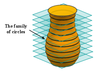
Fig. 1 Axial discretization of the general cutter surface
In five-axis milling, the grazing curve is the set of points on the cutter surface that remain on the envelope surface. As shown in Fig. 2, it divides the cutter’s surface into two parts. The one in orange facing the cutting direction is defined as the front-facing part, which can be actually involved in machining. The other one in light grey is defined as the back-facing part, which is impossible to engage with the in-process workpiece.
As for the primitive circle on the cutter surface, it is spilt into two partial arcs by the grazing points. The solid one shown in Fig. 2 is named as the feasible contact arc (FCA) since it locates at the tool front-facing part. Given that the CWEs are the subsets of the tool front-facing part rather than the back-facing part, determination of the FCA helps us to obtain CWEs in a more efficient way.
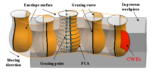
Fig. 2 Illustration of the FCA and CWEs in five-axis milling
As illustrated in Fig. 3, the tool motion is usually represented by two guiding curves  and
and  [30]. To describe the instantaneous cutter position and orientation during NC machining, the moving tool coordinate frame
  is set up at . Its axises are determined as follows
 , (1)
, (1)
where  represents the tool axis orientation at time t with
  .
.
|
(a) |
(b) |
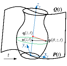
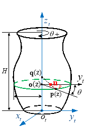
Fig. 3 The enveloping characteristic of the rotary cutter undergoing general spatial motion
When the cutter moves with respect to time t, the point on the cutter surface can be expressed as
 , (2)
, (2)
with  ,
,
 .
.
According to ref. [31], we have the expression of the intersection point between the normal vector of point  and tool axis
 , (3)
, (3)
 .
.
Then, the unit normal vector at the point is
 .(4)
.(4)
The moving speed of the point  on the tool axis is determined by the equation
 .(5)
.(5)
According to the envelope condition for the surface of revolution proposed by Gong et al. [31], the grazing point should meet the following equation
 . (6)
. (6)
By substituting Eq. (4) and (5) into Eq. (6), we have
 , (7)
, (7)
with  .
.
Eq. (7) can be written in the following form
 , (8)
, (8)
 .
.If  ,
,  can be resolved from Eq. (8) as follows:
 . (9)
. (9)
Substituting  ,
,  and a given height z back into Eq. (2), we can get closed-form solutions of two grazing points on the corresponding primitive circle.
Based on the fact that the FCA locates at the front along the moving direction, each point  on the FCA should satisfy the following condition:
 . (10)
According to Eq. (2) and Eq. (9), the FCA of the cutter at axis height  , as shown in Fig. 4, can be expressed as
 . (11)
Hence, according to Eq. (11), the family of FCAs at any CL can be generated, which is then used as the primitive to extract CWEs.
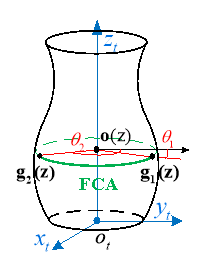
Fig. 4 Illustration of the feasible contact arc
3 Arc-Surface Intersection Method to Calculate Cutter-Workpiece Engagements
The conventional methods to extract CWEs in five-axis milling usually need to update the workpiece at every CL, which is quite computational memory and time consuming. As the FCA is used as the primitive to extract engagement arcs, there is no need to update workpiece during the material removal process unless the cutter moves to the next tool path. As shown in Fig. 5, the entry/exit angles can be determined according to the circumferential angles of endpoints of the engagement arc in red, and there may be more than one pair of entry/exit angles at each axis height. Hence, in this section, a vector  is built to store the entry/exit angles of engagement arcs, which is then used to create the CWE map.
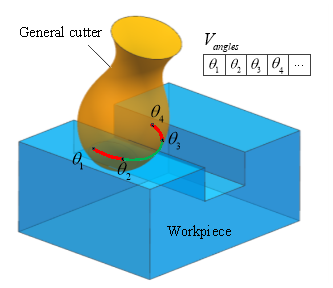
Fig. 5 Illustration of storing engagement angles in a vector
3.1 Intersection of FCA with Workpiece Surfaces
To extract CWEs, we first intersect the FCA with workpiece surfaces to obtain the part of boundary points of engagement arcs. As the workpiece is usually comprised of polygons, quadric surfaces and polynomial surfaces, this paper focuses on the intersection problem of arcs with these three types of surface. It is worth noting that the intersection of the arc with polygon or quadric surface can be analytically computed.
3.2.1 Intersection of Arc with Polygon
Polygon is represented by a list of n vertices:  . The plane of the polygon is defined by the following algebraic equation:
 , (12)
where  is a point on the plane which can be determined by selecting an arbitrary vertex, and
  is a normal vector of the plane which is computed using the cross product of the vectors formed by that vertex and its neighbors.
Substituting Eq. (11) into Eq. (12) yields
 . (13)
Similar to the solving method of Eq. (6), we can analytically obtain at most two intersection points. An even-odd rule algorithm is adopted to determine whether the intersection point is within the boundaries of the polygon [32]. If any intersection point lies inside the polygon, add the corresponding circumferential angle  into .
3.2.2 Intersection of Arc with Quadric Surface
The general implicit form for a quadric surface can be compactly represented as
 , (14)
with  ,
,  .
.
The intersection of the arc with a quadric can be computed by substituting the homogeneous form of Eq. (11) into Eq. (14):
 . (15)
The above equation can be simplified into the following form:
 . (16)
Set  , Eq. (16) can be transformed to a quartic equation of the form
 . (17)
The above equation can be solved analytically by means of a method discovered by Lodovico Ferrari (http://mathworld.wolfram.com/QuarticEquation.html). There are at most four solutions of , which are then added into .
3.2.3 Intersection of Arc with Polynomial Surface
Polynomial surface is commonly used in computer graphics, as it offers great flexibility and precision for handling both analytic and modeled shapes. Its common types include Bézier surfaces, B-spline surfaces and non-uniform rational B-spline (NUBRS) surfaces. The NURBS technique is the only expression standard in STEP (ISO, 1991) for free-form curves and surfaces and gives the uniform mathematical expression for all graphics [33]. Hence, in this section, NURBS surface is taken into account.
A NURBS surface of degree p in the u direction and degree q in the v direction is a bivariate vector-valued piecewise rational function of the form
 , (18)
where  denote a bidirectional control set,
  are the weights,
  and
and  are the non-rational B-spline basis functions.
Then, the intersection of the arc with a NURBS surface can be computed by simultaneously solving Eq. (11) and Eq. (18) using Newton iteration [32]. To improve the computational efficiency, a hierarchy of axis-aligned bounding boxes (AABB) is used which allows for quick rejection and thus can help avoid many expensive intersection computations [34]. If any intersection point is obtained, add the corresponding circumferential angle into .
3.2 Determination of Whether the Endpoint of FCA is Inside the Workpiece Volume Based on Distance Fields
Since it is not enough for the extraction of engagement arcs merely to use the circumferential angles of the intersection points, it is necessary to determine the inclusion relation between the endpoint of the FCA and the workpiece volume. As for the arbitrary endpoint  , a signed Euclidean distance field [35]
  , which defines the minimum distance from to the boundary of workpiece
  , is calculated to determine whether lies inside . It can be represented as follows
 , (19)
where  is the Euclidean norm,
  denotes the boundary of . To improve the computational efficiency, an octree bounding volume hierarchy is used to obtain spatial localization of geometric operations [36]. If the endpoint lies inside the workpiece , add the corresponding circumferential angle into .
3.3 Creation of the CWE Map
There may be multiple engagement arcs corresponding to each primitive circle on the cutter surface, as shown in Fig. 6, where the red arcs denote the engagement arcs. Each engagement arc has its corresponding entry/exit angle. From Fig. 6, it can be found that the entry/exit angles occur in pairs in ascending order. Since obtained above is an unordered list, we first sort it from small to large. Then each pair of entry/exit angle can be obtained by taking each element out of in sequence. Plotting these angles corresponding to each axis height in the two-dimensional space and connecting these angles using linear interpolation, we get the CWE map as shown in Fig. 7.

Fig. 6 Illustration of engagement arcs and immersion angles
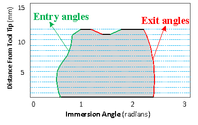
Fig. 7 Illustration of the CWE map
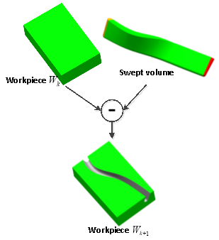
3.4 Updating Workpiece
The swept volume (SV) of a cutter is defined as the totality of all points that belong to the trace of a cutter entity moving along an arbitrary path. It can be modeled as the volume generated by an envelope surface, an initial cutter portion and a final cutter portion along the cutter configurations [37]. According to Eq. (9), note that  is a function of the parameter
  and
and  . Then, by substituting Eq. (9) into Eq. (2), the parametric expression of the envelope surface is obtained as follows:
 . (20)
By stitching the envelope surface with the ingress surface on the initial cutter and the egress surface on the final cutter, the SV is formed as follows:
 , (21)
where  denotes the ingress surface with
  ;
;  denotes the envelope surface with
  ;
;  denotes the egress surface with
  .
.
After the current tool path ends, the workpiece needs to be updated for the CWE calculation of the next tool path. The updated workpeice,  , is obtained through performing Boolean subtraction of the SV from the workpiece
  , as shown in Fig. 8.
The whole algorithm of extracting CWE maps in five-axis milling is summarized as follows.
Algorithm (The arc-surface intersection method to extract CWE maps)
 ;
;Geometry parameters of a cutter;
 .
.
2.For each cutter location 
3.For each axis height 
4.Generate the FCA
5.Determine engagement angles using arc/surface intersection approach
6.Extract entry/exit angles of CWEs
7.End for
8.Generate the CWE map 
9.End for
10.Update workpiece
11.End for
4 Implementation
In order to demonstrate the validity of the ASIM, two example cases are introduced and tested here. The first example shows a finishing machining in five-axis milling of a staircase workpiece with a conical cutter. The second one is a roughing machining of an integral impeller which is one of the most complex milling process. For comparison, the resolution of axial dispersion for all cases is set to 0.1mm. The tests are performed using C++ programming and the commercial 3D module ACIS (the Spatial Company) on a PC with a 3.0 GHz AMD Athlon (TM) X4 640 processor and 6.0 GB RAM.
4.1 Verification by a Vericut Based System
To verify the effectiveness of the ASIM, a test system has been assembled using an OptiPath application programming interface (API) of Vericut (http://www.cgtech.com) which is designed to enable an interface between Vericut and customized plug-in tool path optimization programs. Vericut uses a discrete workpiece model (Z-buffer) to obtain the in-process geometry of the workpiece. CWEs are extracted as a raster bitmap by intersecting the rays cast from a grid of points on the plane perpendicular to the feed direction with the cutter surface and the workpiece volume. Moreover, the output raster bitmap needs to be further processed into the CWE map that can be used in the force prediction model. The CWE calculation method of the test system is the same as that in the Manufacturing Automation Laboratory’ Virtual Machining Interface (MAL-VMI). Since ref. [28] validates its proposed parallel slicing method by comparing with the MAL-VMI, it is reasonable to choose this Vericut based system as a good benchmark. For the following case tests, the grid resolution is set to 0.1mm.
4.2 Examples and Discussion
Example 1. A staircase workpiece corresponding to a designed part, as shown in Fig. 9(a), is chosen to be tested. The workpiece model which results from three axis rough milling only comprises of flat faces. We generate the finishing tool paths with a conical cutter of bottom diameter  , half taper angle
  and height
  by using the commercial software Siemens-NX 8.5. For the first tool path which comprises of 54 CLs, the CWE map calculated by the ASIM at CL#7 is compared with that obtained from the Vericut based system, as shown in Fig. 9(b). The computing time of both methods versus number of CL is illustrated in Fig. 10. The computation time of the proposed method for all CLs is about 21.86s, while the Vericut based system takes only about 7.45s. However, it is worth mentioning that our method generates more smooth and accurate boundary of CWEs.
|
(a) |
(b) |
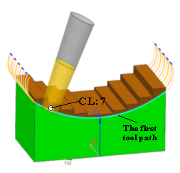
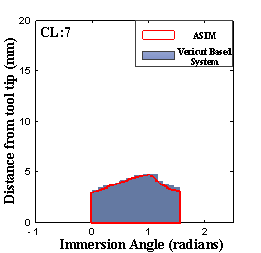
Fig. 9 (a) Test model 1 with a conical cutter; (b) CWE map at CL#7
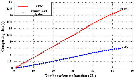
Fig. 10 Comparison of computing time between the ASIMand the Vericut based method
Example 2. A rough machining for five-axis milling of an integral impeller is used as a case study shown in Fig. 11. The tool used for roughing is a taper ball-end mill of ball radius  , half taper angle and height
  . For the first tool path, CWE maps calculated by the ASIM at CL#27 and CL#453 are compared with these obtained from the Vericut based system, as shown in Fig. 12(a). Before implementation of the second tool path, the workpiece is updated through subtraction Boolean operation of the initial workpiece and the swept volume of the first tool path. Then, comparisons have been made at CL#190 and CL#556, as depicted in Fig. 12(b). Fig. 13 illustrates the computing time of both methods versus number of CL. For the first rough tool path, it can be seen that the computational efficiency of both methods is equivalent. However, for the second rough tool path, the Vericut based system takes about 5mins to calculate all of the CWE maps, while the ASIM takes as much as 29mins. The decrease in efficiency is caused by the increased intersections between the FCA and the updated workpiece, the boundary surfaces of which is polynomial surfaces.
|
(a) |
(b) |
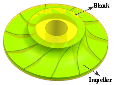
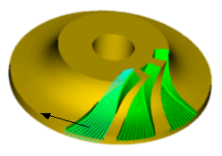
Fig. 11 Simulation of rough machining of an integral impeller. (a) The design model and the blank model of the impeller; (b) Tool paths shown in Vericut
|
(a) |
|
(b) |

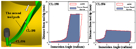
Fig. 12 CWE maps for (a) the first tool path and (b) the second tool path
|
(a) |
(b) |

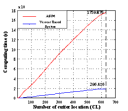
Fig. 13 Comparison of computing time between the ASIM and the Vericut based method for (a) the first tool path and (b) the second tool path
Although computationally slower than the Z-buffer based method, the proposed ASIM captures the boundaries of CWEs more accurately as shown in Fig. 9 and 10. The main error sources of the Vericut based system are summarized as follows. First, the serrated boundaries on the borders of CWE maps result from the digitization effect when projecting the Z-buffer engagement grid into cylindrical coordinates. Second, the engagement angles out of the range of  can’t be captured since this method assumes tool axis staying fixed at each path segment during five-axis milling.
As for the workpiece merely comprising of flat and quadric surfaces, the ASIM shows a high efficiency of computation. It is worth mentioning that this method also gives the user a degree of flexibility by setting the resolution of axial discretization to achieve the required computational efficiency or accuracy.
In this work, a new arc-surface intersection method (ASIM) to extract CWE maps for supporting five-axis cutting force prediction is presented. First, the cutter rotary surface is discretized into a family of cross-sectional circles along the tool axis. Then, the feasible contact arc (FCA), which is the forward part of the circle at each axis height, is analytically determined. By intersecting the FCA with worpiece surfaces and determining the inclusion relation between the endpoint of the FCA and the workpiece volume, the boundaries of engagement arcs are obtained. Finally, entry/exit angles of CWEs at each axis height are extracted to plot a CWE map. To demonstrate the validity of the proposed method, comparisons have been made with a Vericut based system by implementing several case tests. Several distinct features of the present approach are summarized as follows.
- For a whole tool trajectory, since the FCA is extracted to intersect with workpiece surfaces for calculating CWEs, we don’t need to update the workpiece for every CL as the conventional studies did. Hence, it saves a lot of computational time and memory usage.
- As the boundaries of engagements at each axis height can be accurately determined using arc/surface intersections, this method well solves the problems of low efficiency and poor robustness in solid modeling methods and low precision in discrete methods.
- For five-axis milling of the workpiece merely comprising of flat and quadric surfaces, usually existing in rough milling process and semi-finishing process, the CWE map can be analytically obtained with the ASIM.
- The ASIM gives the user a degree of flexibility by setting the resolution of axial discretization to achieve the required computational efficiency or accuracy.
- When the resolution of axial discretization of the ASIM is set to be consistent with the milling force model, the engagement of each cutting element can be calculated accurately. Hence, although the ASIM is a semi-discrete method, it is compatible well with the force model without loss of precision.
In order to integrate this method into a virtual machining system for five-axis milling of arbitrary workpieces, additional work should be done to deal with self-intersecting envelope surfaces. Furthermore, the computational speed needs to be improved by optimization of C++ program and implementation of parallel algorithm.
This work was partially supported by the National Natural Science Foundation of China under grant No. 51325502, the National Key Basic Research Program under grant No. 2011CB706804, and the Science & Technology Commission of Shanghai Municipality under grant No. 13JC1408400.
[1] A. Lasemi, D. Xue, P.H. Gu, Recent development in CNC machining of freeform surfaces: A state-of-the-art review, Computer-Aided Design, 42 (2010) 641-654.
[2] L.M. Zhu, H. Ding, Y.L. Xiong, Simultaneous optimization of tool path and shape for five-axis flank milling, Computer-Aided Design, 44 (2012) 1229-1234.
[3] R.F. Harik, H. Gong, A. Bernard, 5-axis flank milling: A state-of-the-art review, Computer-Aided Design, 45 (2013) 796-808.
[4] Z.L. Li, L.M. Zhu, Envelope surface modeling and tool path optimization for five-axis flank milling considering cutter runout, Journal of Manufacturing Science and Engineering, Transactions of the ASME, 136 (2014) 041021.
[5] L.M. Zhu, Y.A. Lu, Geometric conditions for tangent continuity of swept tool envelopes with application to multi-pass flank milling, Computer-Aided Design, 59 (2015) 43-49.
[6] S.K. Gupta, S.K. Saini, B.W. Spranklin, Z. Yao, Geometric algorithms for computing cutter engagement functions in 2.5 D milling operations, Computer-Aided Design, 37 (2005) 1469-1480.
[7] L. Tunc, E. Budak, Extraction of 5-axis milling conditions from CAM data for process simulation, The International Journal of Advanced Manufacturing Technology, 43 (2009) 538-550.
[8] G. Kiswanto, H. Hendriko, E. Duc, An analytical method for obtaining cutter workpiece engagement during a semi-finish in five-axis milling, Computer-Aided Design, 55 (2014) 81-93.
[9] E. Aras, H.-Y. Feng, Vector model-based workpiece update in multi-axis milling by moving surface of revolution, The International Journal of Advanced Manufacturing Technology, 52 (2011) 913-927.
[10] B. Fussell, R. Jerard, J. Hemmett, Modeling of cutting geometry and forces for 5-axis sculptured surface machining, Computer-Aided Design, 35 (2003) 333-346.
[11] D. Roth, F. Ismail, S. Bedi, Mechanistic modelling of the milling process using an adaptive depth buffer, Computer-Aided Design, 35 (2003) 1287-1303.
[12] L. Zhang, J. Feng, Y. Wang, M. Chen, Feedrate scheduling strategy for free-form surface machining through an integrated geometric and mechanistic model, The International Journal of Advanced Manufacturing Technology, 40 (2009) 1191-1201.
[13] J. Li, Y. Yao, P. Xia, C. Liu, C. Wu, Extended octree for cutting force prediction, The International Journal of Advanced Manufacturing Technology, 39 (2008) 866-873.
[14] R.B. Jerard, R. Drysdale III, K. Hauck, B. Schaudt, J. Magewick, Methods for detecting errors in numerically controlled machining of sculptured surfaces, Computer Graphics and Applications, IEEE, 9 (1989) 26-39.
[15] S.R. Maeng, N. Baek, S.Y. Shin, B.K. Choi, A Z-map update method for linearly moving tools, Computer-Aided Design, 35 (2003) 995-1009.
[16] S.R. Maeng, N. Baek, S.-Y. Shin, B.K. Choi, A fast NC simulation method for circularly moving tools in the Z-map environment, in:Â Geometric Modeling and Processing, 2004. Proceedings, IEEE, 2004, pp. 319-328.
[17] R.X. Zhu, S.G. Kapoor, R.E. DeVor, Mechanistic modeling of the ball end milling process for multi-axis machining of free-form surfaces, Journal of Manufacturing Science and Engineering, Transactions of the ASME, 123 (2001) 369-379.
[18] L.Q. Zhang, Process modeling and toolpath optimization for five-axis ball-end milling based on tool motion analysis, The International Journal of Advanced Manufacturing Technology, 57 (2011) 905-916.
[19] Z.Y. Yao, Finding cutter engagement for ball end milling of tessellated free-form surfaces, in:Â ASME 2005 International Design Engineering Technical Conferences and Computers and Information in Engineering Conference, American Society of Mechanical Engineers, 2005, pp. 121-127.
[20] E. Aras, D. Yip-Hoi, Geometric modeling of cutter/workpiece engagements in three-axis milling using polyhedral representations, Journal of Computing and Information Science in Engineering, Transactions of the ASME, 8 (2008) 031007.
[21] Z.Y. Yao, A. Joneja, Computing cutter engagement values in milling tessellated free-form surfaces, Journal of Computing and Information Science in Engineering, Transactions of the ASME, 10 (2010) 041005.
[22] A. Spence, Y. Altintas, A solid modeller based milling process simulation and planning system, Journal of Manufacturing Science and Engineering, Transactions of the ASME, 116 (1994) 61-69.
[23] A.D. Spence, F. Abrari, M.A. Elbestawi, Integrated solid modeller based solutions for machining, Computer-Aided Design, 32 (2000) 553-568.
[24] I. Lazoglu, Y. Boz, H. Erdim, Five-axis milling mechanics for complex free form surfaces, CIRP Annals-Manufacturing Technology, 60 (2011) 117-120.
[25] E. Aras, A. Albedah, Extracting cutter/workpiece engagements in five-axis milling using solid modeler, The International Journal of Advanced Manufacturing Technology, (2014) 1-12.
[26] E. Aras, D. Yip-Hoi, State-of-the-art in geometric modeling for virtual machining, in:Â ASME 2012 International Design Engineering Technical Conferences and Computers and Information in Engineering Conference, American Society of Mechanical Engineers, 2012, pp. 737-750.
[27] Y. Yang, W.H. Zhang, M. Wan, Y.C. Ma, A solid trimming method to extract cutter-workpiece engagement maps for multi-axis milling, The International Journal of Advanced Manufacturing Technology, (2013) 1-13.
[28] W. Ferry, D. Yip-Hoi, Cutter-workpiece engagement calculations by parallel slicing for five-axis flank milling of jet engine impellers, Journal of Manufacturing Science and Engineering, Transactions of the ASME, 130 (2008) 51011.
[29] W. Ferry, Y. Altintas, Virtual five-axis flank milling of jet engine impellers-part I: mechanics of five-axis flank milling, Journal of Manufacturing Science and Engineering, Transactions of the ASME, 130 (2008) 011005.
[30] L.M. Zhu, G. Zheng, H. Ding, Y.L. Xiong, Global optimization of tool path for five-axis flank milling with a conical cutter, Computer-Aided Design, 42 (2010) 903-910.
[31] H. Gong, N. Wang, Analytical calculation of the envelope surface for generic milling tools directly from CL-data based on the moving frame method, Computer-Aided Design, 41 (2009) 848-855.
[32] P. Schneider, D.H. Eberly, Geometric tools for computer graphics, Morgan Kaufmann, 2002.
[33] L. Piegl, W. Tiller, The NURBS book. 2nd, New York: Springer, 1997.
[34] W. Martin, E. Cohen, R. Fish, P. Shirley, Practical ray tracing of trimmed NURBS surfaces, Journal of Graphics Tools, 5 (2000) 27-52.
[35] A. Sullivan, H. Erdim, R.N. Perry, S.F. Frisken, High accuracy NC milling simulation using composite adaptively sampled distance fields, Computer-Aided Design, 44 (2012) 522-536.
[36] H. Erdim, A. Sullivan, Cutter workpiece engagement calculations for five-axis milling using composite adaptively sampled distance fields, Procedia CIRP, 8 (2013) 437-442.
[37] S.W. Lee, A. Nestler, Complete swept volume generation, Part I: Swept volume of a piecewise C-1-continuous cutter at five-axis milling via Gauss map, Computer-Aided Design, 43 (2011) 427-441.
[*] Corresponding author, Email: [email protected]