Automated Power Pole Photography via Helicopters
Fugro Roames aims to automate the process of acquiring high resolution pictures, to reduce the risk and cost associated with helicopter based pole top inspection. The project will focus on acquiring previously worked algorithms, as well as the introduction of model predictive control, to automate the overall process, while also presenting a working prototype to simulate the operation of the intended product.
The following proposal will aim to describe the intended topic and scope, while also reviewing background information on aerial asset management and autonomous aerial photography related to the project. The report will also highlight all achievable milestones, and their respective tasks, within the project plan; as well as present a detailed OH&S risk assessment of the projectâĂŹs practical and non-practical work.
The work completed during the semester, will hope to provide sufficient groundwork for automated aerial asset management procedures, within the electrical distribution industry.
Accurate and effective asset condition management is important to ensure the longevity of an electric distribution network, while maximising its performance and operational efficiency.[1] At present, an efficient and cost effective method to test the integrity of a network, requires the use of a human-piloted helicopter and a photographer to capture high resolution images of power poles and their subcomponents [2]. Fugro-Roames, a company which currently provides this to its customers, aims to reduce the risk and cost associated with helicopter based pole top inspection, by replacing the photographer with an automated camera gimbal to capture high resolution pictures of the network.
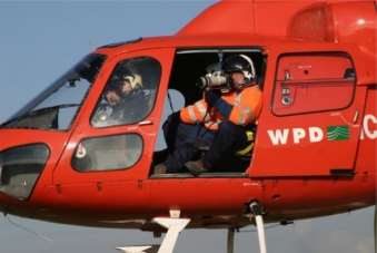
Figure 1.1: Power Pole Photography [1]
Automated aerial asset management in the context of this proposal refers to the use of aerial platforms, to asses specific assets in an easy and cost-efficient manner, without the need of manual involvement. Unfortunately, and as it will be discussed in Chapter 3, the project topic is a form of technology that has not been widely researched; however, various methods of aerial asset management, such as helicopters, UAVs or drones, do exist and are currently in use within the industry.
2.1 Project Outline
It is the purpose of this project to develop a Receding Horizon Planner (RHP) in order to automate power pole photography using camera gimbal system. The RHP will based on the algorithms created by Dr. Michael Kearney, which provide a solution to the photograph feasibility, photograph scheduling, and gimbal trajectory planning problems [3]. For validation, the developed planner will be tested using simulation flight data provided by Fugro-Roames. Further testing will include the implementation of the RHP into a gimbal prototype, where sensitivity analyses and assessment of the initial assumptions will be completed to determine the project’s limitations and outline recommendations for future work. A more defined project plan will be described in Chapter 4 below.
2.2 Motivation for Automated Aerial Asset Management
In order to overcome the limitations associated with conventional asset management methods, a high resolution image capture system was developed and is now used to aid in the inspection, assessment and maintenance of electric distribution networks [4]. However, the overall cost associated with this method, outweights its improved efficiency, as it involves specialized labour (photographers) and the use of helicopters to complete the required task [5]. The motivation to introduce an automated aerial asset management system, requires for the reduction of risks and overall cost associated with the current model, as well as improving the quality and selection of photographs taken.
2.3 Project Aim, Objectives & Intended Scope
Since the project, and all information available, are sponsored and provided by FugroRoames, the aims and objectives have been defined by the company’s desires for the finished product. Therefore, the aim and proposed purpose of the project is to reduce the cost and risk associated with helicopter based pole top inspection, with the use of a Receding Horizon Planner (RHP) that automates the movement and control of a camera gimbal system. Along with the proposed project aim, multiple objectives must also be met whilts completing the work required. These include improving the algorithms created by Dr. Kearney, obtaining accurate efficiency gains for the RHP, designing and building a working gimbal prototype to be used for testing, and providing sufficient ground work for actual on-site testing and implementation, with the use of a helicopter, of the RHP beyond the project. Similar to the project’s aim and objectives, the intended scope has also been shaped by the company’s desires for the final product. Therefore, the scope can be outlined as:
- Review of background information and related work
- Adaptation of algorithms created by Dr. Kearney
- Development of Receding Horizon Planner
- Design and build of a gimbal prototype
- Planner implementation and testing
- Analysis of results
- Sensitivity analysis
- Assesment of project’s assumptions
- Evaluation of project and suggestion for future work
- Possible gimbal rig implementation and on-site testing
Taking into account the scope described above, it seems logical to break the project into three specific sections; planner development and testing, prototype design and testing, and thorough result analysis. The development and testing of the Receding Horizon Planner involves the improvement of existing control algorithms, to implement and verify its overall efficiency, using available and provided data. The design and testing of the gimbal prototype, which should resemble the actual gimbal rig, involves the use of the developed Receding Horizon Planner to validate and improve previously obtained results. Finally, thorough result analysis requires the breakdown of the planner and obtained results, to find how assumptions, parameters and particular components were affetcted.
Although automated aerial asset management is a form of technology that has not been widely researched, the following chapter will provide a complete review of background literature which would closely resemble the general subject matter. The review will be broken into two sections; aerial asset management, and autonomous aerial photography and gimbal control. Previous work related to these topics will be presented, reiterated and reviewed, focusing on sources related to asset management within the electric power distribution industry.
3.1Aerial Asset Management
Aerial asset management , within the electric power distribution industry, has been implemented to replace conventional asset management and inspection methods, and provide a fast and accurate way to determine any defects that could be present.
Whitworth et al. [6], in a work sponsored by EA Tecnology, propose the use of a helicopter-mounted camera to capture and store visual information, in order to enhance the inspection of overhead power lines. In order to reduce ‘camera shake’ and partially automate the inspection process, the authors recommend the use of an acquisition system, which finds and locks the camera to the location of the powerline, followed by a recursive algorithm that tracks the powerline smoothly, despite the translation of the helicopter.
Similarly, Earp et al. [1][4] describe an aerial inspection technique, which was also developed by EA Technology, that uses high resoluion images to perform a detailed condition assessment on electrical towers within a distribution network. The authors break down the helicopter based condition assessment, which is considered an improvement from the video inspection method in [6], to include four different parts:
- Pre-flight Planning: Inspection requirements, photographic sequences, camera trajectories; as well as current wind and weather conditions, natural and man-made ground feature, and the locations of the electrical towers, are all taken into account during the pre-flight planning.
- Helicopter Inspection and Picture Acquisition: A high resolution digital camera is used to take a set number of images, per tower, to meet the inspection requirements. Satellite-based Global Positioning System (GPS) and moving map displays are used to georeference each photograph taken, back to the tower.
- Image Processing, Analysis and Condition Assessment: Captured images are examined and given a Condition Rating (CR), typically on a scale of 1 to 4 (1 describing best condition, 4 describing worst condition). The uniformity of the assessment, determined by the individual DNO’s requirements, is ensured by this critical step and therefore requires for a detailed condition assessment criteria, application-specific workstations, and accurate in-house training programme for assessors.
- Condition Based Risk Management (CBRM): A process developed by EA Technology, it combines practical and theoretical knowledge about a specific asset, along with maintenance experience, in order to define its current condition.
Taking a different approach, N. Ellis [7] investigates the use of Unmanned Aerial Vehicles (UAVs) to inspect power transition lines. The author investigated the cost, risks and overall efficiency that comes with the use of UAVs, searching for low budget automation strategies to be designed and tested. Unfortunately, due to government regulations and the high capital and operating cost of the UAV, lead the author to the conclusion that the technology is not feasible at the current time.
As outlined by most of the sources presented, the introduction of aerial asset management techniques, has made a big improvement on the inspection, assessment and maintenance of an electrical distribution network. Whilst most models present techniques that far surpass conventional inspection methods, the cost that comes with the involvement of specialized labour and helicopters, leaves little room for errors and inconsistent results. However, although the implementation of an UAV was not possible due to the introduction of new risks, the automation techniques, presented in [7], can be applied to previously discussed aerial photography techniques, and mitigate/remove any currently involved risks.
3.2Autonomous Aerial Photography and Gimbal Control
Autonomous aerial photography and control, within the electric power distribution industry, is not a topic that has been widely researched or implemented. However, the use of a camera and aerial images to predict and control the movement of UAVs is something that is commonly discussed and will therefore, be the main focus for this section.
E. Skjong et al. [8] investigate the recent commercial availability of UAVs within Search and Rescue (SAR) and Search and Tracking (SAT) applications. The authors then focus on the development of a SAT system, which is able to steer the UAV and focus the gimbal attitude on regions and objects of interest respectively, with the use of Model Predictive Control (MPC). The overall process is made autonomous by allowing computer vision to work directly with the UAV autopilot and MPC, so objects can be simultaneously detected and tracked in an efficient manner.
Similarly, C.E. Lin and S. Yang [9] explore the use of UAVs to detect and track specific objects, with the help of aerial photography and camera gimbal control. The authors implement the use of an Inertial Measurement Unit (IMU), which consist of a gyroscope, accelerometer, and magnetometer, along with an Attitude and Heading Reference System (AHRS), to determine and ensure that the angles of the camera gimbal are in the correct reference frame. Both [8] and [9] use Global Positioning System (GPS) to determine the location of both the UAV and the target, using this relationship to implement a reliable autopilot flight control for target detection and photography.
R.J. Rajesh and C.M. Ananda [10] move away from controlling the camera gimbal, attached to a UAV, and focus on stabilizing its movement to ensure that clear photograph and/or video footage is taken. The use of Proportional-Integral-Derivative (PID) controller is recommended by the authors, to compensate for the vibrations and gust, as well as control the position of the camera by stabilizing the movement of the gimbal. Manually tuning the controller’s parameters is not recommended, as the process is considered time consuming and tedious, instead, the authors recommend the use of Particle Swarm Optimization (PSO) as the preferred algorithm to complete this task.
Uncertainty and disturbances are mentioned, but not properly investigated in [9], [8] and [10]. A. Ashok et al. [11] investigate the external disturbances that affect the UAVs, as well as the dynamic and parametric uncertainties that arise in the mathematical autonomous model when subjected to a number of operating conditions. The authors reiterate previous approaches taken to design a robust control system, including the use of a PID controller for linear [12] and linearized [13] models, as well as the use of a Linear Quadratic Gaussian (LQG) controller [14] in the presence of uncertainties, before the Uncertainty and Disturbance Estimation (UDE) method is chosen to synthesize the required controller.
The control of a camera gimbal, as outlined by most of the sources above, is necessary in order to ensure the accuracy of photographs or video that is captured by the UAV. Although the use of conventional control methods is described above, only [8] focuses on the use of MPC, which is closely related to the project, to ensure that the UAV is able to detect and track objects efficiently and simultaneously.
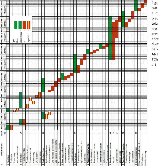
A clear representation of the project’s tasks, has been outlined as a comprehensive project plan from the first to the final day of employment at Fugro-Roames. A visual representation and description of the plan is used to illustrate the timeline of the project, including all achievable milestones, which are related to the aims, objectives and intended scope of the project, discussed in section 1.2.
4.1Visual Representation of Project Plan
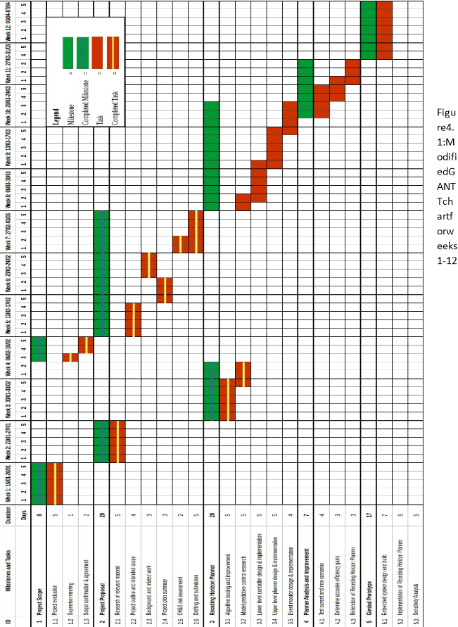
The use of a modified GANTT chart was implemented to showcase the proposed flow of the project, from the first to the last day of employment. The timeline is hence separated into 24 weeks that are broken into 5 days, in the same manner as the business week format, where the project milestones and their corresponding tasks are allocated a precise number of days in which work is scheduled to take place.
Green solid bars represent the project’s milestones, where red solid bars indicate their respective tasks. The progress of the overall project is tracked by the completion of every achievable milestone, which can only be completed by first completing their respective sub tasks. Completed milestones are shown with a blue line through the green bar, and completed tasks are shown with a yellow line through the red bar.
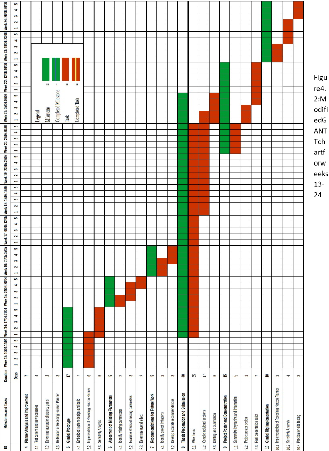
Weeks 1 to 12, as shown in Figure 4.1, represent the core work to be completed, as Milestones 3-5 directly relate to the aims, objectives and intended scope of the project. Weeks 13 to 22, as shown in Figure 4.2, outline the analysis and completion of the final pieces of assessment, including the thesis report and demonstration, which require the content from previous milestones to be completed. Weeks 23 to 24, also shown in Figure 3.2, outline a possible Milestone that can be completed until the final day of employment at Fugro-Roames. This milestone does not affect the previous pieces of assessment; however, it will provide the company with important information that could prove vital to the future of the project.
4.2Milestone & Task Breakdown
Milestone 1: Project Scope
The project scope is necessary to determine the project’s main objectives, and will therefore guide the work to be completed throughout the semester. To ensure all expectations are met, and the appropriate time is given to all project milestones, an agreement between academic and industry supervisors is necessary.
|
Task |
ID |
Days Description |
|
|
Project evaluation |
1.1 |
5 |
Evaluate the requirements of the project, including potential goals and outcomes. Collect all necessary information to present during the supervisor meeting. |
|
Supervisor meeting |
1.2 |
1 |
Meet with the project’s academic and industry supervisors to discuss the project scope, and agree on the due dates for all pieces of assessment. |
|
Scope confirmation & agreement |
1.3 |
2 |
Compile a detailed scope which highlights the project’s objectives, as discussed during the supervisor meeting. |
Resources
- Workspace with an available computer
- Availability from both supervisors to organize a meeting
Milestone Hazards and Risks
Milestone 1 is essential to the project. Any delay could be considered a minor, but possible risk, as it affects the progress of the overall project. If this issue becomes bigger, and the project scope cannot be defined, then it can be classified as a major risk and mitigation strategies should be taken immediately.
Clear communication between all parties involved, can reduce and remove the possibility of the identified risks from occurring.
Milestone 2: Project Proposal
The project proposal is the first piece of assessment, which must be completed as part of the responsibilities for completing the project placement. The report highlights the work from Milestone 1, as it expands on the agreed aims and objectives, outlines the background information related to the project’s main topics, and presents a visual and a clear representation of the project plan. A detailed OH&S risk assessment, which analyses the potential risk involved with the project’s practical work, and any potential equipment used, will also be included in the proposal.
|
Task |
ID |
Days Description |
|
|
Research of relevant material |
2.1 |
5 |
Find background information and prior art related to the project’s main topic. |
|
Project outline and intended scope |
2.2 |
4 |
Expand on the project’s scope decided in Task 1, expanding on the project’s aims and objectives. |
|
Background and related work |
2.3 |
3 |
Summarize and expand on the material obtained from Task 2.1. |
|
Project plan summary |
2.4 |
3 |
Provide a detailed project plan, with logically ordered tasks and their respective milestones. |
|
OH&S risk assessment |
2.5 |
2 |
Compile an OH&S risk assessment, which highlights the project’s practical work and equipment used. |
|
Drafting and submission |
2.5 |
5 |
Assemble the proposal’s individual sections, review the written report and submit via Turnitin. |
Resources
- Completion of Milestone 1
- Confirmation of university assessment due dates
- OH&S risk assessments, regarding the use and control of the gimbal rig
Milestone Hazards and Risks
The project proposal relies mostly on individual and previously completed work, however, certain sections require resources which are not readily available. The most significant obstacles, which would require mitigation, are the confirmation of all university assessment due dates and the risk assessments completed for the gimbal rig, which might be used during the project.
Clear and constant communication with the university’s course coordinator, as well as the personnel in charge of the gimbal rig, is essential to mitigate and prevent any issues that could affect the completion of the project proposal.

Milestone 3: Receding Horizon Planner
Milestone 3 is the first milestone that uses the algorithms created by Dr. Kearney to develop an on-line planner that controls the photograph scheduling plan and the movement of the gimbal throughout the event horizon. The completed Receding Horizon Planner will involve the use of a low level controller, an upper level planner, and an event monitor, to be used in Milestones 4→7.
|
Task |
ID |
Days Description |
|
|
Algorithm testing and improvement |
3.1 |
5 |
Improve the current photograph feasibility algorithm, and test its efficiency. |
|
Model predictive control research |
3.2 |
5 |
Find related material to be used when designing the Receding Horizon Controller. |
|
Lower level controller design & implementation |
3.3 |
5 |
The gimbal and camera are robustly controlled by the photograph scheduling algorithm chosen by the upper level planner. |
|
Upper level planner design & implementation |
3.4 |
5 |
Implemented the improved algorithm from Task 3.1 to generate a plan that the system will follow over a prediction horizon. |
|
Event monitor design & implementation |
3.5 |
4 |
Connect the results from Tasks 3.3 and 3.4 so that the plan is implemented and changed after certain events occur. |
Resources
- Programming and modelling software
- Access to the project’s repository and previous work
Milestone Hazards and Risks
The progress of Milestone 3 could be significantly affected, if access to the necessary repositories and previous work is delayed. As previous algorithms are necessary to the development of the Receding Horizon Planner, the completion of the project would be significantly impacted.
Clear communication with the right personnel can help mitigate this issue before it affect the timeline and progress of the project.

Milestone 4: Planner Analysis and Improvement
Rigorous testing of the developed Receding Horizon Planner is required to find the necessary efficiency gains, so the planner can be implemented on the project’s physical equipment. Data obtained from Fugro Roames, as well as the analysis and reiteration of the testing completed, will be completed to improve the found controller gains.
|
Task |
ID |
Days Description |
|
|
Test current and new scenarios |
4.1 |
4 |
Implement the Receding Horizon Planner on several simulated scenarios, using data received from Fugro Roames. |
|
Reiteration of Receding Horizon Planner testing |
4.2 |
3 |
Fix any errors found in Task 4.1 and repeat the tests. |
|
Determine accurate efficiency gains |
4.3 |
3 |
Determine the required controller gains which provide the most accurate results. |
Resources
- Completion of Milestone 3
- Sufficient testing data provided by Fugro Roames
Milestone Hazards and Risks
The lack of testing data used to complete this milestone, is a minor risk that could affect the project. Requesting said data ahead of time, would ensure that it is ready for when testing of the Receding Horizon Planner begins, leaving the project timeline unaffected.

Milestone 5: Gimbal Prototype
Milestone 5 marks a key point in the project, as the implementation of the Receding Horizon Planner on a working prototype is essential to the project’s success. The design of the prototype will be based on the actual gimbal rig owned and created by FugroRoames, to facilitate the implementation of the planner for further testing, at the end of the project.
|
Task |
ID |
Days Description |
|
|
Embedded system design and build |
5.1 |
7 |
Design, build and combine the mechanical, electrical, and software components of the prototype. |
|
Implementation of Receding Horizon Planner |
5.2 |
6 |
Test the Receding Horizon Planner using the gimbal prototype. |
|
Sensitivity Analysis |
5.3 |
5 |
Identify and vary the dominant parameters, testing and improving the Receding Horizon Planner where possible. |
Resources
- Completion of Milestone 4
- Mechanical, electrical and software design software
- Working space and necessary build equipment
- Development of testing scenarios
Milestone Hazards and Risks
Milestone 5 introduces the use of practical equipment to design, test and build each component of the gimbal prototype. The misuse of the practical equipment, and the lack of component testing, are immediate risks to the completion of the prototype. Following the risk assessment outlines on Chapter 4, as well as completing the required testing before the Receding Horizon Planner is implemented, can help mitigate the risks described and prevent possible delays.

Milestone 6: Assessment of Project’s Assumptions
As previously shown by Dr. Kearney, on the initial report he completed for Fugr-Roames, the introduction of the Receding Horizon Planner required changes to the initial assumptions made when designing the project’s photograph allocation and gimbal control algorithms.
The change and/or the addition of assumptions, by analysing the project’s missing parameters is, therefore, also essential when validating the results obtained in Milestone
5.
|
Task |
ID |
Days Description |
|
|
Identify missing parameters |
6.1 |
2 |
Determine the project’s missing parameters based on the assumptions made by Dr. Kearney on his report. |
|
Evaluate the effects of missing parameters |
6.2 |
3 |
Assess how the model is affected by each missing parameter. |
|
Update the project’s assumptions |
6.3 |
2 |
Compose a list of updated assumptions based on the results from tasks 6.1 and 6.2, to be used on further work. |
Resources
• Completion of the Sensitivity Analysis Task within Milestone 5
Milestone Hazards and Risks
The risks to Milestone 6 are relatively small, where the largest possible problem involves the inability to identify the effects of the project’s missing parameters. Keeping a record of all parameter changes/assumptions made during previous tests is the best solution to mitigate/prevent this issue.
Milestone 7: Project Evaluation and Recommendation for Future Work
Identifying the project’s limitations is an important process, as it allows recommendations for future work to be made and included on the final thesis report.
|
Task |
ID |
Days Description |
|
Identify project’s limitations |
7.1 |
3 List the project’s limitations, based on the results from Task 6. |
|
Develop accurate recommendations |
7.2 |
3 Expand on previous work and results from Tasks 6.1 to 6.3, including 7.1, to develop accurate recommendations for future work. |
Resources
- Development of the Receding Horizon Planner
- Sensitivity analysis of the gimbal prototype
- Completion of Milestone 6
Milestone Hazards and Risks
The completion of Milestone 7 is only affected by the work done in previous milestones. If previous tasks are delayed, any future recommendations run the risk of not being completed.
To prevent this from affecting the final stages of the project, the plan/timeline outlined should always be followed, noting where/if any delay happens so its impact can be reduced.

Milestone 8: Thesis Preparation and submission
The second and highest weighted piece of assessment involves the combination of all previous work, combined into a concise and comprehensive thesis report. Milestone 8 has been given a significant amount of time, to ensure that the thesis is polished to reflect a high standard of work.
The information written and compiled for the thesis, will be summarized and later used to complete the project poster and script as part of the requirements for Milestone 9.
|
Task |
ID |
Days Description |
|
|
Write the thesis’ individual sections |
8.1 |
35 |
Write the thesis |
|
Compile individual sections |
8.2 |
17 |
Collate each thesis section progressively. |
|
Drafting and submission |
8.3 |
5 |
Review the work done in Task 8.2, present a draft to both supervisors and submit via Turnitin. |
Resources
- Development of the Receding Horizon Planner
- Sensitivity analysis of the gimbal prototype
- Assessment of project’s assumptions and limitations
Milestone Hazards and Risks
The biggest risk to completing and submitting the thesis, is the delay in the project schedule and how it can affect the content that is required is included in the final report. Previous mitigation strategies are essential to reduce the effect of this risk.
If there is not enough time to complete all milestones, written material, should focus on the work completed up to the implementation of the gimbal prototype, so the quality of the final report isn’t heavily affected and key content can still be presented.

Milestone 9: Project Poster and Demonstration
The project demonstration is the third and final piece of assessment for the project. It uses summarized information, from the work completed in Milestone 8, to design a poster that focuses on the project’s scope, background information and overall results.
|
Task |
ID |
Days Description |
|
|
Summarize key topics and information |
9.1 |
5 |
Review and find the key topics from the completed thesis report |
|
Project poster design |
9.2 |
3 |
Design a poster that highlights the project’s goals and achievements, as well as the relevant background information. |
|
Final presentation script |
9.3 |
7 |
Write and practice the script to be used during the presentation. |
Resources
- Summary of key information from final thesis
- Agreement on demonstration date from all parties involved
Milestone Hazards and Risks
The time given to complete this milestone depends on the date where both supervisors and parties involved in the project can meet. Unfortunately, depending on the date chosen, the quality of the final product and thesis report can be affected, if the necessary time isn’t given to design the project poster and prepare for the demonstration.
To mitigate this issue, constant communication with the project’s supervisors is required to agree on a demonstration date that both, allows the thesis report to be submitted, and provides the time required to complete all tasks necessary to achieve Milestone 9.

Possible Milestone: Gimbal Rig Implementation
Once all pieces of assessment have been completed and submitted, the developed Receding Horizon Planner can be implemented into the gimbal rig. The process would mirror that of Milestone 5, with the possibility of actual on-site testing to detect and capture images of electrical street poles.
|
Task |
ID |
Days Description |
|
|
Implementation of Receding Horizon Planner |
10.1 |
3 |
Implement the results obtained from the gimbal prototype, updating any necessary paramaters. |
|
Sensitivity analysis |
10.2 |
4 |
Identify and vary the dominant parameters, testing and improving the Receding Horizon Planner where possible. |
|
Practical on-site testing |
10.3 |
3 |
Test the entire system by detecting and capturing images of street poles. |
Resources
- Submission of all pieces of assessment
- Results and data gathered from Milestone 5
- Necessary software and dynamics to control gimbal rig
- Permission and safety induction for possible on-site testing
Milestone Hazards and Risks
As safety is one of the most important aspects of any engineering project, the use and testing of the gimbal rig, will require necessary permissions and inductions to be granted and completed. For this possible milestone to be completed before the project time ends, all permissions and required inductions should be obtained and completed, by communicating with the appropriate Fugro Roames personnel, before any work can begin.
A comprehensive Occupational Health and Safety (OH&S) risk assessment was completed to highlight all risks and hazards involved in both practical and non-practical project work. The scope, related activities and specific risks/hazards are outlined within both risk assessments.
The risk matrix, which is used to classify and assesses the probability, severity and overall risk, can be found in Appendix A.
5.1Risk Assessment for Practical Project Work
The completed risk assessment for all project based practical work is shown below in Table 5.1. The scope of the risk assessment includes the design and build of the gimbal prototype, as well as the implementation of the Receding Horizon Planner on the gimbal rig for on-site testing. Only the risks directly related to the participation of the above procedures, will be assessed and outlined below.
The design of the mechanical and electrical components, which will form part of the gimbal prototype, requires the use equipment including a soldering iron, a 3D printer and various hand tools within a secure lab environment at the university.
The gimbal rig is a complex piece of equipment designed and developed by Fugro-Roames. Controlling and changing default settings, both manually and electronically, is essential before the Receding Horizon Planner can be implemented. Furthermore, the use of specific equipment to properly mount the rig onto a car, is required before any on-site testing can begin.
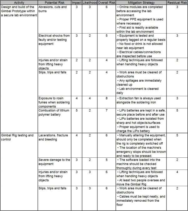
Table 5.1: Risk Assessment of Project Work in a Lab Environment
5.2Risk Assessment for Non-Practical Project Work
The outline and assessment of all risks associated with non-practical work, completed within an office environment, are shown in Table 5.2. The scope of the risk assessment focuses on the short and long term hazards that may arise when designing, testing and improving the Receding Horizon Planner, analysing data obtained from completed sensitivity analyses, as well as the time required to prepare and submit all pieces of assessment related to the project.
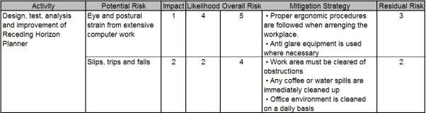
Table 5.2: Risk Assessment of Project Work in an Office Environment
.
In conclusion, the report outlines the intended plan for a project with the topic of automated power pole photography via helicopters. The motivation behind automated asset management was explained, focusing on the safety and cost improvements to the current technology, while also presenting the project’s aim, objectives and intended scope.
A detailed review of background information and work related to the project was also completed, with specific emphasis on aerial asset management and autonomous aerial photography and gimbal control.
A visual representation of the project plan using a modified GANTT chart, describes the flow of work to be completed from the first to last day of employment at Fugro-Roames, 16th January to 30th June respectively. All necessary tasks were individually described and brought together to fulfil the project’s achievable milestones, where the resources, possible risks and mitigation strategies are also examined.
Finally, a comprehensive OH&S risk assessment with the necessary control measures and mitigation strategies for all practical and non-practical work is also presented.
- G. Earp, R. Eyre-Walker, A. Ellam and A. Thomas, “Advanced aerial inspection and asset management of electricity towers” in Proc. of the 12th Int. Conf. on Transmission and Distribution Construction, Operation and Live-Line Maintenance, 16-19 May 2011, Rhode Island, United States of America [Online]. Available: IEEE Xplore, http://www.ieee.org. [Accessed: 20 Jan. 2017]
- Fugro Roames, “Asset Condition Management,” Service Sheet Roames, 2015. [Online]. Available: https://www.fugro.com. [Accessed: 20 Jan. 2017]
- M. Kearney, “Planning and control fro automated aerial photography of power-pole tops,” The University of Queensland, Brisbane, QLD, Jan. 2016.
- G. Earp, “Condition Based Risk Assessment of Electricity Towers using High Resolution Images from a Helicopter” in Proc. of the 18th Int. Conf. on Electricity Distribution, 6-9 June 2005, Turin, Italy [Online]. Available: IEEE Xplore, http://www.ieee.org. [Accessed: 20 Jan. 2017]
- C. Rich, “Unmanned Aerial Vehicles and the Future of Asset Management,” M.B.A. thesis, Simon Fraser University, Burnaby, BC, Canada, 2015.
- C.C. Whitworth, A.W.G. Duller, D.I. Jones, “Aerial Video Inspection of Overhead Power Lines” in Power Engineering Journal, vol. 15, no. 1, pp 25-32, Feb. 2001.
- N. Ellis, “Inspection of Power Transmission Lines using UAVs,” B.E. thesis, University of Southern Queensland, Brisbane, QLD, Australia, 2013.
- E. Skjong, S.A. Nundal, F.S. Leira, T.A. Johansen, “Autonomous search and tracking of objects using model predictive control of unmanned aerial vehicle and gimbal: Hardware-in-the-loop simulation of payload and avionics” in Proc. of Int. Conf. on
Unmanned Aircraft Systems (ICUAS), 9-12 June 2015, Denver, CO, USA [Online]. Available: IEEE Xplore, http://www.ieee.org. [Accessed: 21 Jan. 2017]
- C.E. Lin, S. Yang, “Camera gimbal tracking from UAC flight control” in Proc. of the CACS Int. Conf. on Automatic Control (CACS), 26-28 Nov. 2014, Kaohsiung, Taiwan [Online]. Available: IEEE Xplore, http://www.ieee.org. [Accessed: 24 Jan. 2017]
- R.J. Rajesh, C.M Ananda, “PSO tuned PID controller for controlling camera position in UAV using 2-axis gimbal” in Proc. of Int. Conf. on Power and Advanced Control Engineering (ICPACE), 12-14 Aug. 2015, Bangalore, India [Online]. Available: IEEE Xplore, http://www.ieee.org. [Accessed: 15 Feb. 2017]
- A. Ashok, D. Kumari, K. Satish, “Robust control of UAVs using uncertainty and
Disturbance Estimation” in Proc. of the Int. Conf. on Industrial Instrumentation and Control (ICIC), 28-30 May 2015, Pune, India [Online]. Available: IEEE Xplore, http://www.ieee.org. [Accessed: 13 Feb. 2017]
- B. Kada, Y. Ghazzawi, “Robust PID Controller Design for an UAV Flight Control
System” in Proc. of the World Congress on Engineering and Computer Science, Vol II, 19-21 Oct. 2011, San Francisco, USA [Online]. Available: IEEE Xplore, http://www.ieee.org. [Accessed: 13 Feb. 2017]
- C. Hancer, K.T. Oner, E. Sirimoglu, E. Cetinsoy, M. Unel, “Robust Hovering Control of a Quad Tilt-Wing UAV” in Proc. of the 36th Annual Conf. on IEEE Industrial
Electronics Society, 7-10 Nov. 2010, Glendale, AZ, USA [Online]. Available: IEEE Xplore, http://www.ieee.org. [Accessed: 13 Feb. 2017]
- G.X. Athanasius , J.G. Zhu, A.G. Sreenatha, “Robust Control of Unmanned Aerial
Vehicles”in Proc. of the Int. Conf. on Advances in Computing, Control, and Telecommunication Technologies, 28-29 Dec. 2009, Trivandrum, Kerala, India [Online].
Available: IEEE Xplore, http://www.ieee.org. [Accessed: 13 Feb. 2017]
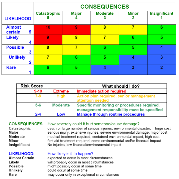
Figure A.1: Risk Matrix for assessment of possible OH&S risks