Circuit Protection and Utilisation of Electricity
 Task 1
With the aid of suitable diagrams, describe in detail, the construction and operating principles of the following circuit breakers.
Include in your description the advantages and disadvantages of each
a) Oil circuit breaker
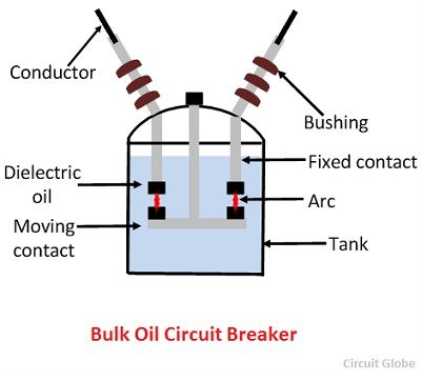
An oil circuit breaker or ‘OCB’ is a type of device which uses different kinds of oils as insulating materials/dielectrics in order to reduce the arc when activated. The circuit breaker will have two contacts that are forced to separate while being submersed in oil, the oil is there to evaporate any heat produced by the arc when the breaker is tripped. An OCB is made up of a metal tank to contain the oil and contacts, contacts for carrying the current and the oil which is the insulating material that stops an arc occurring. The operation of this type of breaker is simple, the contacts start off in the closed position so that the circuit is complete and when a fault occurs the contacts are then forced apart causing an arc to form. Sometimes an arc can emit heat which can damage the circuit and machinery, this is why we use the oil to evaporate the heat. The oil will be turned into gas(hydrogen) and then slowly displace any oil left, the arc will be extinguished when the contacts move far away from each other. The OCB contacts can sometimes get burnt when arcing has occurred and carbon can form in the area around the contacts. The carbon makes the oil lose dielectric strength and therefore means that the circuit breaker is less effective at breaking the current. The OCB needs to be drained and refilled when it has tripped, also the contacts need to be closely inspected for burning or carbon build up. There are two types of oil circuit breaker:
– Bulk Oil- This is a circuit breaker that requires larger amounts of oil so that the arc can be extinguished. These circuit breakers can also be known as ‘dead tank'(Circuit globe, 2016) because the tank is positioned at ground potential. If the voltage is higher then more oil will be required as the arc will be stronger and harder to extinguish. Another use of this circuit breaker is to insulate all live parts in the breaker from the earth.
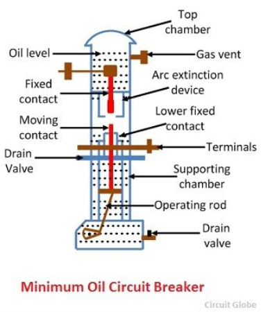 – Minimum Oil- This circuit breaker aims to use the minimum required oil that is possible, instead of extinguishing the arc completely using oil it also uses porcelain. The porcelain insulates the circuit breaker live parts from the earth. The chamber of the breaker is lined with ‘bakelised’ (Circuit globe, 2016) paper, this paper has good mechanical and electrical properties. The tube moves vertically in order to break contact, when the contacts start to separate then oil is forced into the cylinder to reduce arcing.
The advantages of OCB’s:
– Due to the oil having a ‘high dielectric strength'(Circuit globe, 2016) it can be used as
insulation once the arc has been dealt with.
– The hydrogen produced due to the evaporation of the oil is good for cooling the device and
diffusing.
– The oil creates a clearing in the conductors and the earth components.
The disadvantages of OCB’s:
– The oil is flammable which means that fires are able to be started with it.
– The oils dielectric strength decreases due to the carbon particles that pollute it.
– Since the tank isn’t always air tight this leaves room for dangerous mixture of air which could
result in explosive substances being created.
-If the tank needed is large then it can be expensive.
b) Vacuum interrupter
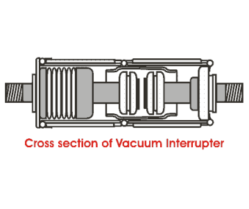
A vacuum circuit breaker or VCB is a type of circuit breaker that uses a vacuum to extinguish the arc. This works best on weaker voltages, as higher voltages will be too strong to extinguish. The breaker can be made of steel and consists of a chamber which is the vacuum interrupter, the material for the contacts needs to be perfect as otherwise there won’t be an effective connection. The application of this type of circuit breaker is to switch HV devices, they are as effective as SF6 breakers which have a big chance of leakage. The reason it is better than other circuit breakers is because when the contacts separate inside the vacuum they have a greater dielectric strength which builds up so that it is thousands of times higher than normal circuit breakers.
Advantages to a VCB:
– Since there isn’t any material or substance inside the chamber there’s no risk of fire
– They have a good service life as they have minimal parts
– Due to the fact that it doesn’t use harmful gases or substances it is safer for people to work
on and for the environment.
– The replacement and maintenance is much easier.
– they can be used repeatedly.
– There are no gases inside which means that there is no room for gas emission leakage.
Disadvantages to a VCB:
– when the vacuum has been damaged, failed to extinguish the arc or loses the vacuum it cant
be repaired on site. This is due to the complex design and conditions that it needs to be
fixed.
– the vacuum interrupter will need ‘surge suppressors‘ (Hub pages, January 2 2014) that are in
parallel with the phase interrupters with low currents.
– they are uneconomical if only small quantities are being made
c) HRC liquid fuse
A HRC liquid fuse is a high voltage fuse which have a relatively high current rating and breaking capacity. This means that the fuse can be used in some high voltage applications, high voltage fuses need specific designs so that they can handle it without breaking. There are two types of HRC fuse:
Liquid type HV HRC fuse:
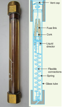
This type of fuse is filled with a fluid called ‘Carbon tetrachloride‘ (Circuit globe, 2016) and they can be used for a large number of high voltage applications. They can protect circuits that have a 400 A rating or higher, their breaking capacity is around 6100 A when used on a circuit with a 33KV supply. This fuse is made up of a glass tubing filled with the above fluid and it has brass caps on either end. There is also a fuse link which gets fixed to one of the caps and then the other end is attached to a bronze spiral fixed onto the other cap. When the limit of current is exceeded then the fuse link will be blown, this will retract the spring so that it hits a liquid detector. When the arc is created and extinguished a small quantity of gas will be produced, fuses aren’t normally used as the first protective method for a circuit. The circuit will have other circuit breakers, if the circuit breakers fail then the fuse will blow.
 Advantages:
– cheaper than other circuit protecting devices
-Maintenance is not required
– Is able to be used in high and low voltage applications
– The operation/breaking of the fuse is automatic
Disadvantages:
– the fuse needs be rewired or replaced when blown
– the fuse can sometimes have tripping time issues when dealing with different voltages.
Cartridge type HV HRC fuse:
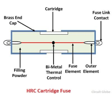
This type of fuse is very similar to low voltage fuses however there is a specific component that makes it effective at extinguishing high voltage arcs. The only difference in the design I that the wire is wound into a ring shape so that the corona effect can be avoided, the corona effect is ‘the ionization of a fluid surrounding a conductor that is electrically charged‘ (wiki user, 2016). some applications may require two fuses to be put in parallel, one of them will have a low resistance and the other a high resistance so that the low resistance will blow first and slightly reduce the stress on the circuit when it breaks. This type of fuse can be used up to 33kv as they have a breaking capacity of about 8,760 A.
Advantages:
– They don’t deteriorate over time
– They have a high speed of operation
 – No maintenance is required
– It is cheaper than other methods
– They can be used for both high and low voltage applications
Disadvantages:
– After it has blown it must be replaced
– when an arc occurs it produces heat energy which means that it is a fire hazard and can
damage some of the components inside
d) HRC expulsion fuse
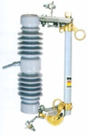
This type of fuse uses gases produced by the arc and its lining to extinguish the arc, it also is vented to let the gas out. The fuse link can be surrounded by liquid which turn into gas such as ‘boric acid’ (Wiki User, 2016) when the fuse is blown the heat from the arc will make the boric acid change into gas. The gas will then quickly extinguish the arc, the gas also will explosively burst out the ends of the fuse and this is the reason they must only be used outside. There is usually a type of pin so that you can manually blow all three phases in case only one had gone. This fuse can be used with very high amperage as well as low voltage.
Advantages:
– No maintenance is required
– Cheaper than other types of circuit breaker
– Simple installation
Disadvantages:
– Can be dangerous when blown as there is an explosive part in the process
– Damage to other devices may occur if they are in close vicinity to the fuse at time of breaking
– Needs to be replaced and repaired when blown
 Task 2
- Produce suitably labelled diagrams and produce a detailed explanation of the principles of operation of an inverse definite minimum time relay.
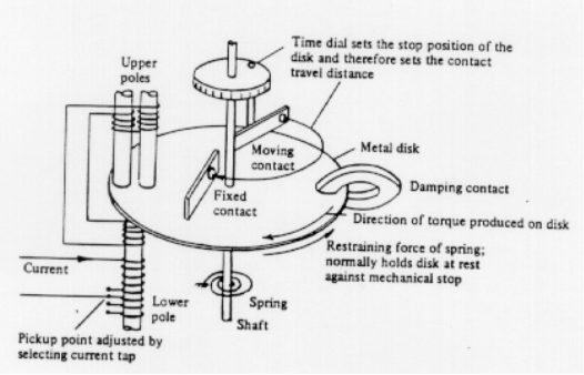
An inverse definite minimum time relay AKA IDMT relay is a circuit protection device that consists of an upper electromagnet which has two windings, There is a primary and a secondary. The primary winding is attached to the current transformer that is on the line that is in need of protection and has eight tappings. The tappings are connected to a plug which sets the bridge by the number of turns that will be used, the settings then can be adjusted so that required current setting can be achieved. The secondary winding is then energized by the induction effect and is wound over the limb in the middle of the upper electromagnet, it also spreads over the limbs of the lower electromagnet. There is a disc which has flux leakages, the flux leakage comes from the upper electro magnet and it is in phase with a disc on the lower electromagnet. Te disc has a spindle which has a moving contact that connects two of the fixed contacts when it has rotated into a certain position. The setting of this position or angle varies, it can vary from 0 to 360. This device operates during overload conditions, when over current occurs this device will protect the circuit from any damage that may be caused.
-
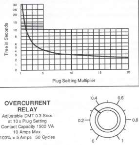 An 11 kV three phase system develops a 159 MVA line to line short circuit. The system is protected by a scheme using 500/1 ratio Current Transformer rated at 5 A and IDMT relays. Determine the operating time for the relays if the time multipliers were set to 0.45 s and the plug setting was 120 %.
IDMT relay current characteristic curve
Task 3
- Describe with the aid of diagrams the importance of properly earthing equipment.
- With the aid of diagrams describe the following methods of earth fault protection:
- Earth fault relay.
- Residual current device.
Use examples of earth fault protection at your place of work.
a)
There are many risks within my workplace however one of the main risks is electricity, it is very important that I am protected from this risk as it can cause severe injury or fatality. To ground something means to attach a path for the electrical current to return to the ground safely. This will stop the current using us as paths, when a short circuit occurs the current will find the easiest way back to the ground. There are a few main reasons for grounding all electrical equipment:
– Prevent Damage to equipment, injury or death– This is the most important reason in my
opinion as it will literally protect our lives. The most important aspect to work is safety which
means making all equipment safe for use, we do this by earthing it and doing PAT testing. PAT
testing (Portable appliance testing) is in place to make sure that the equipment works and
will not hurt or damage itself/others. Electricity is very dangerous and can arc if not earthed
or correctly encased, it can cause death and injuries which could affect the rest of someone’s
life.
– Electrical overload protection– this means that it will protect us from any surges that may
occur, this could be a surge in current or perhaps a lightning strike. If the equipment is
earthed then the surge will go straight into the ground, if however it isn’t then it would go
into whatever was in contact with the equipment.
– Direction of electricity- The electricity will have a clear, safe path to the ground which means
it is much safer for people to use the equipment. The current will be able to move safely and
efficiently throughout the system without risk of hurting or damaging the circuit/person using
it.
– Stabilization of voltage levels– Grounding also makes sure that all the currents and power are
distributed around the circuit to their proper places. This means that there is little room for
over current and the circuit being broken, it provides a reference point for the voltage sources
in the circuit system.
– The earth is the best conductor– the earth is a very good conductor, the electricity which is
trying to get to earth will also take the route with the least resistance. This is why we are
perfect for connecting the appliance to the earth, grounding the system will give the
electricity a better path.
Grounding can be done individually at peoples houses by use of a metal rod or extendable metal pipe that runs into the house from the underground water supply. There are different types of Earthing/Grounding:
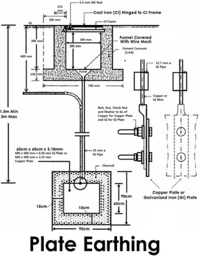 – Plate type- this is a method where a small metal plate is buried no more than 3 meters below the housing, it is connected to piping which is then connected to the houses service panel.
– Pipe type- the pipe or rod will have a set of terminals that copper conductors can connect to, the copper conductors then will be put into the service panel for the house, this would ground the houses electrical appliances.
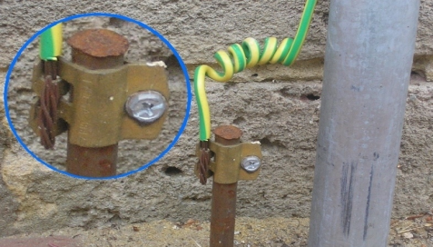
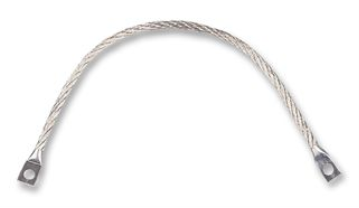 – Strip/Wire Earthing- These are used between casings of metal equipment to earth/ground the device or machinery. It can be attached from the casing to another piece of metal that goes into the ground.
b)
i) Earth Fault Relay
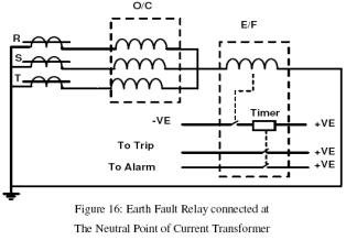
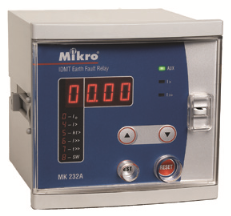
A relay is a device that is able to detect unordinary conditions within the system, it enables the correct circuit breakers to trip when over current is detected. Most relays operate with the induction principle, this means that when the relay operates its contacts are closed in the circuit and the passage of current within the coil in the trip circuit activates a plunger. The plunger then will activate the appropriate circuit breaker to trip, this means that the area of fault in the system is disconnected safely. This type of relay is basically there to trip the circuit breaker if there is a fault with the earthing pathway, this could be damaged cable or a build up in resistance causing excessive current. The induction principle consists of moving parts such as an aluminium disc fixed onto a shaft and this rotates on two bearings between the poles of an electromagnet and ‘damping magnet’. The electromagnet gets wound and has seven taps. The seven taps are on the front of the panel, the tap that is required can be chosen by pushing in the plug. There is a setting called the pick-up current which can be varied via the use of a plug multiplier. The pick-up current values of earth fault relays are normally quite low.
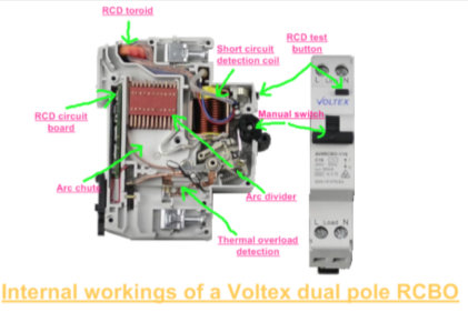
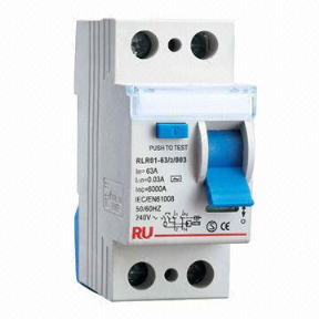
ii) Residual current device-
A residual current device AKA an RCD is an electrical device that breaks a circuit when it senses that the current is unbalanced or overloaded between the line and neutral conductors. These devices are more effective at keeping the operator safe than fuses and circuit breakers are, they will prevent fatalities if someone were to touch a live part. They do this as they are highly sensitive and will switch off electrically if there is any fault. They make sure that the circuit is switched off if it detects electricity flowing down a wrong path, this could be caused by a cut or damaged wire coming into contact with something other than the severed cable. There are a few types of RCD’s:
– Fixed- This device is used in consumer units and will protect a group of circuits or individual ones if that is what is required. It will protect anything in the circuit including any appliances attached to the circuit, the fixed RCD will offer a very quick protection from fatality or severe injury.
– Portable- This device is able to be plugged into the socket and will protect the equipment, lead and person touching the equipment. However it wont protect the whole circuit, if someone were to touch another part of the circuit they may still get electrocuted.
– Socket-outlet- This is basically a socket with a built in RCD, it can be used as a regular socket would be. It doesn’t protect the whole circuit, it will protect the equipment plugged in and the leads, as well as the person touching the equipment.
References:
– Circuit globe (2016) Oil Circuit Breaker [online] Available: http://circuitglobe.com/oil-circuit-breaker.html [Accessed: 21/12/2016]
– http://hubpages.com/technology/Vacuum-Circuit-Breakers-Advantages-Disadvantages
– https://en.wikipedia.org/wiki/Corona_discharge
– https://www.mepits.com/tutorial/472/Electrical/Electric-Fuse
– http://www.platinumelectricians.com.au/blog/importance-grounding-electrical-currents/
– http://www.electricaltechnology.org/2015/05/earthing-and-electrical-grounding-types-of-earthing.html
– http://www.allinterview.com/showanswers/90014/what-is-idmt-relay-how-it-works.html
– http://cindulkar.tripod.com/lab13.pdf
– http://www.itmikro.com/app/webroot/UploadedContent/images/pro_3_1.png
– http://www.electricalsafetyfirst.org.uk/guides-and-advice/electrical-items/rcds-explained/