CompInnova System Project Requirements
The CompInnova project is focused upon the development of an innovative inspection methodology, with automated and manual capabilities, for any type of composite and metallic aircraft structures. Within this report, project requirements and specifications related to structural integrity, damage repair and development of a vortex robot, are presented and discussed in the following order:
- A qualified Phased Array (PA) method related to the structural integrity approach, is an advanced non-destructive testing method used to detect component failures (i.e. cracks), and can be used to assess the component condition. It is presented in chapter 2.
- An Infrared Thermography (IRT) method, also related the structural integrity approach, is used to determine the presence of flaws by monitoring the flow of heat over a surface, and is presented in chapter 3.
- A Damage Tolerance (DT) structural integrity assessment technique is used to fracture load for a specified defect size, and predict the required length of time for a sub-critical defect to grow to the size that causes fracture at given load. The DT is presented in chapter 4.
- Following the structural integrity assessment, a preliminary assessment of the specifications of the repair module of the vortex robot is presented in chapter 5, with the repair module envisaged to perform scarfing or stepped lap repairs on composites as well as bonding repairs on metals.
- The repair module, as well as the structural integrity assessment systems, is a part of a vortex robot, for which a detailed overview of the existing state of the art in NDT robotic technology is presented in chapter 6. In addition, an overview of the determined project requirements and specifications related to the proposed NDT novel vortex robotic mechanism is presented as well.
The project requirements for the CompInnova system has been drafted and agreed by all the participants in this document.
Phase Array (PA) technique is an advanced non-destructive testing method used to detect component failures. PA is used for in service inspection and characterization of faults in metallic, as well as composite components. PA uses transducers made up of individual elements that can each be independently driven, by which it is able to decrease the complexity and the handling of an ultrasonic testing system. The PA probes are connected to specially adapted drive units with independent, simultaneous emission and reception along each channel.
2.1 Phased Array Transducer
The PAUT transducer should be a linear array transducer with number of elements between 16 and 128 and the central frequency should be ranged between 2 and 5 MHz so that minimum ultrasonic inspection requirements are satisfied for a range of different material structures. The element pitch would be between 0.5 and 0.8 mm (high resolution probe) and it will be defined according to the minimum detectable defect, the properties of the scanned samples and the quality of the acquired ultrasonic images. Furthermore, the array aperture (coverage area rate parameter) and the element length would be finally determined according to the final array specifications. The moving velocity for the array would be approximately 20mm/sec and dependent on the characteristics of the scanned sample for flat or slightly curved surfaces.
The transducer would be able to be connected with any PA system via an array interface (i.e. 128 element Hypertronics generic array interface) with cable length that will be defined by the needs of the outdoor inspections required (i.e. required manipulation region of the probe, especially on large structures) and the quality of ultrasonic data acquired. The array should have the capability to directly be integrated in any manipulator for automated operation however it would also be possible to be used in manual inspection procedures with encoded capability along the movement direction with the aid of special encoding configuration that will be continuously attached with the array. By marking the necessary inspection paths on the sample surface and performing several passes with the probe, large areas can be inspected manually. The wedge coupled with the array would have a thickness between 30 and 35 mm and with an angle that is always dependent on the inspection sample thickness (i.e. make sure that reference signals like front and back wall echoes are detectable and visible) and the type of incidence wave required (i.e. longitudinal or shear wave). Precautions will be taken in order to maintain the array at a proper contact arrangement with the testing surface. Water mist, gel or combination of both, are used as a couplant before scanning.
The phased array probe would have potential to be interconnected with PA instruments and effectively all the necessary functions for ultrasonic inspection procedure can be performed by the integrated system, which are:
- automatic recognition of the installed ultrasonic transducer by the PA instrument,
- ultrasonic array element configuration,
- system calibration for reliable inspections,
- gathering of acquired ultrasonic data,
- A-scan, B-scan and C-scan imaging of data,
- real time or post processing of acquired data,
- interconnection with manipulators for acquisition of probe X-Y-Z position,
- mapping software development for the acquired ultrasonic data, and
- editing, storing and loading of array configurations.
2.2 Ultrasonic Data Acquisition Mapping Software
Ultrasonic data acquisition mapping software would be developed with the aid of installed software environment (i.e. Labview environment) on the PA instrument and therefore processing and visualization of the acquired ultrasonic data can be obtained. All the element firing and probe-wedge configurations can be modified within the software environment. More specifically the user determines the scanning method (linear, half step or FMC) and the number of active elements. This is a procedure that allows the user to adjust all the involved parameters of the ultrasonic hardware by carefully interfacing with the software.
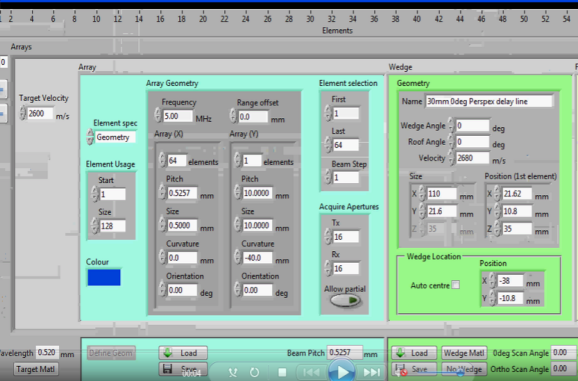
Figure 2.1: Representation of an Ultrasonic Data Acquisition Mapping Software
The parameters of array and wedge operation can be adjusted. Operating frequency, active aperture elements, beam step, acquire elements and wedge geometry can be set according to the inspection requirements. Array and wedge geometries can be saved or loaded.
After the setting of the array-wedge configuration and all the data from PAUT and manipulator are available the scanning can commence. When operating, any type of acquisition display (A scan, B scan or C scan) would be available and so watch the progress of the inspection. Sizing of defects or regions of interest can take place using different image processing techniques or by simply implementing the typical 6db method.
2.3 Conclusion
The PA technique will be employed within the advanced defect detection software for detecting very small size flaws in aircraft structures, while achieving a high POD without increasing the scanning time dramatically. This is achievable with the PA technique, since it is able to reduce the amount of sensors as well as the overall complexity of the system applied, while enabling independent and simultaneous emission and reception along each channel.