Components and Features of Central Locking System
Central locking
The main function of the central locking system is controlling access authorization at all times but it also must cover the following areas: actuation of opening handles or lifting, braking and locking the doors during closing operation.
The central locking system includes following components:
-locking bars on the body pillars,
-doors, door lock mechanism and dedicated mechanical and electrical parts,
-electrical components – required to access authorization facility and radio remote control.
Depending on their location further dividing being made:
-side door assembly,
-trunk assembly,
-hood assembly,
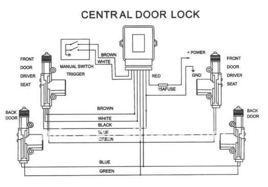
Illustration 1: Central locking system schematic
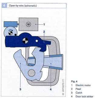
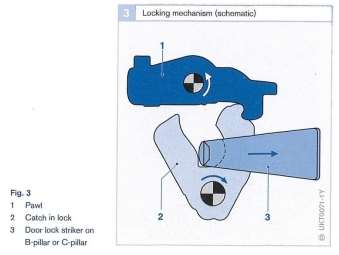 Door assembly consists of catch, pawl and latch. The door lock striker is attached to the body pillar. Under closing operation the door lock striker gets caught by the latch and hold in the closed position and centres the door. The pawl positively locks the catch in position. This lock condition is automatically aborted when opening procedures begin. For this process the forces acting on inner or outer door handle are transferred to the pawl and cause the catch release to open the door. The door lock striker stays in the position while the catch swivels go into an open position.
In a case of operation methods central locking system consists of two types of actuators: electromagnetic and pneumatic.
Electromagnetic actuators rely on solenoids which lock or unlock doors using current going in both directions (open/closed) through an electric module. On this kind of system two types of arrangements are in use. First one uses separate relays for each of action taking by the system. One dedicated to open and another one to close the door. Both of them are controlled by a transistor switching the circuit operated by the capacitor (storage for energy necessary to operate system) which is releasing current necessary to activate the locks. Another type uses two capacitors and two relays working as a tandem. One pair is responsible for locking and another for unlocking. When the circuit is closed a current is discharged from the capacitor and the lock is either opened or closed.
IMAGE
Pneumatic actuators are driven by a pneumatic central unit which controls vacuum/pressure pump. When vacuum is applied actuators acting on mechanism lock or unlock the door. The vacuum pump is driven by electric motor which is working in both directions. Forward rotation creates a compressor action (doors open), while backwards rotation creates vacuum (doors close). Polarity on the electric motor is changed by a change-over control switch.
IMAGE
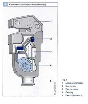
In most modern cars electrical locking system replaced mechanical unit due to a demand for quality and reliability. The main advantages of electrical locking system are:
-symmetrical design,
-smaller and lighter in comparison to a mechanical unit
-only one lock version per vehicle
-individually encoding at the end of the production line
-door handles no longer move
Other supplementary functions, like an interior light or status indicator, can be easily introduced in electrical locking system because the lock is equipped with electronics, which can carry out these functions. Communications with the locks, power supply and security system take place via data can bus system.
Engine immobilisers
An immobiliser is an electronic anti-theft security device which prevents engine start by an unauthorised person unless the correct key or fob is placed in the ignition barrel. If the correct key is used, transponder inside the key sends a signal to the reader which transfer signal to the receiver (ECU). If the signal is recognised by the ECU, the system allows user to start engine. If not the immobiliser disables few car systems necessary to start the engine: usually it is fuel injection, fuel pump and ignition components.

The immobiliser is strongly connected to the car security system, so any unauthorised access to the car that is detected by the security system (movement detectors, infra-red sensor, sonic sensor and many others, depending on the security system) automatically trigger the immobiliser and any other alarm aims such a horn and flashing headlights.
Car alarm can be activated by infra-red signal generated by the fob or a key ring and received by optical sensing unit placed somewhere in the car. Another type is a radio control system. Radio wave is created by the fob or the key and received by car antenna – quite often a car heated rear window. In both examples the signal is unique for each car and only this one signal is recognised by the ECU.
Alarm system uses few different types of sensors to protect the car:
-shock sensor: detecting any vehicle moment
-ultrasonic: car interior is covered by an ultrasonic signal; any change in the strength on the signal pattern activates the alarm
-voltage drop or current drain: any drop of voltage (disconnecting the battery) or current drain (by switching on interior light)
-infra-red: detecting any disruption of the beam transmitted between two points inside of the car
-direct earth contact: detected by the bonnet, boot and door switches when an earth contact happens
Diagnosis and repair defect.
Make: Vauxhall
Model: Vectra B
Year: 1999
After connecting central locking rig to the battery I noticed that the locking system does not work properly. Firstly, I checked voltage on the battery, unfortunately it was too low: -12v. To rectify this I connected the battery to the charger. Since then the central locking system starts to perform quickly and properly. After a short while the system stopped working completely. It didn’t react to the car key fob. First, I checked the battery voltage inside the key. Multimeter showed the voltage of 3v (battery type-CR2032), which is absolutely perfect.
I was looking closely into the key fob for any damage on the electronic circuit or battery holders, but everything was in a proper working order.
After that I measured the resistance of each door and readings on multimeter were as follow:
Nsf-1 ohm,
Osf-1 ohm,
Nsr-1 ohm,
Osr-1 ohm,
According to the Autodata all readings matched the factory range. To be sure about my findings I checked continuity on each of the door and this confirmed my thought that wiring between the doors and the central unit is in a good working order. Last part of my diagnostics was checking the condition of the central unit itself.
Firstly, I connected the multimeter to the port No2 and No8 to check voltage transferred from the battery to the central locking unit. Unfortunately the voltage was 0v. Then I checked continuity on the wiring between the central locking unit and the battery. There was no continuity at all.
My diagnosis: The wiring between the battery and the central locking unit is faulty. To rectify this the faulty wiring needs to be replaced.
Electrical circuit diagram
