Design of Condition Monitoring (CM) system of a Case Study
|
Term / Abbreviation |
Definition |
|
CBW |
Continuous Batch Washer |
|
CM |
Condition Monitoring |
|
DIN |
Deutsches Institut fur Normung (German Institute for Standardization) |
|
FFT |
Fast Fourier Transform |
|
FTIR |
Fourier Transform Infrared Spectroscopy |
|
IR |
Infra-Red |
|
OEM |
Original Equipment Manufacturer |
|
P-F |
Potential to Functional Failure |
|
PM |
Preventive Maintenance |
|
SGS |
Spring Grove Services |
|
TAN |
Total Acid Number |
|
TBN |
Total Base Number |
|
TWF |
Time Wave Form |
|
WDA |
Wear Debris Analysis |
Â
Spring Grove Services has decided to embark on a Condition Monitoring approach for the maintenance of its most critical equipment.
Criticality was established by carrying out a study on the main Utilities and Process systems/machinery.
This report includes data and images from a Thermography study, carried out at SGS, as this type of CM has already commenced. The findings identified in this exercise have highlighted potential points of failure in the Novopac shrink-wrap lines.
Lubrication and Vibration Analysis studies have yet to commence so will be considered from a ‘look-ahead’ perspective. The areas of focus here are the 18 Stage CBW and the Kaeser air compressor respectively. There will be predictions and estimates made on possible findings and required follow-up actions.
The report undertaken here confirms to the author the necessity of introducing CM for equipment that is central to the successful running of the SGS plant in Cork.
Spring Grove Services is one of Ireland’s leading laundry rental service providers. SGS has four major processing sites in Ireland.
The business model functions by supplying linen to customers on a rental basis. This is then collected after use and cleaned before re-supply. Clients are supplied from a pool stock i.e. linen is not specific to any one client.
The plant in Cork, which is featured in our case study, processes on average 330,000kgs of linen per week which equates to approximately 660,000 individual pieces. Run hours are 85 per week. Its customers include Ireland’s biggest hotels and hospitals.
There is a ‘real time’ aspect to this industry in the sense that linen processed today may well be used in a hotel or hospital tonight. This same linen will probably have only arrived in the laundry this morning in a soiled state.
Lengthy batch release times due to quality inspections do not feature as they would in the pharmaceutical and healthcare products industries. This does not mean that there are poor quality standards, it just means that there is a minimum of time to ascertain them.
This super-lean model requires maximum availability of plant equipment so effective maintenance is paramount. The operating context is also a factor in the maintenance strategy: equipment with many moving parts operating in a hot, humid and/or dusty environment.
Preventive and Corrective Maintenance has historically been accepted practice with SGS but Condition Monitoring is coming more to the forefront for the most critical equipment.
SGS is part of the European wide Berendsen group.
The first step in the Condition Monitoring journey was to identify the most critical equipment. This would naturally become the focus of CM.
Appendices A and B illustrate how Utilities and Process systems interact at SGS.
Appendix C explains in detail, using a Criticality Scoring Scheme (Wheelhouse, 2014), how the results in Figure 1 were attained.
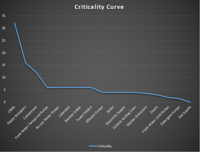
Figure 1: SGS Criticality Curve
Figure 1 trends criticality for the various Utilities and Process systems/equipment in Spring Grove Services.
From Figure 1, we can deduce that the most critical assets are the CBWs, the Plastic Wrappers and the air Compressor. On further analysing the failure modes associated with this equipment, we can decide on where the exact focus of CM will be:
- 18 Stage CBW: This machine is the work horse of the Wash House as it alone processes 50% of the linen. It’s most critical piece of equipment is the drive motor/gearbox assembly. We will apply Lubrication Analysis to the gearbox.
- Plastic Wrappers: These pieces of equipment form the final stage of the laundering process. Failure here creates a severe bottleneck. We will apply Thermographic Analysis to the electrical control panels.
- Air Compressor: If the compressor stops, production stops as there is no redundancy available. We will apply Vibration Analysis to the bearings as they are overdue replacement according to Original Equipment Manufacturer specification.
3.1 Equipment Description
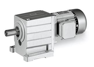
Figure 2: Lenze GST Geared Motor (Source: Geared Motor Spares)
Figure 2 shows the type of geared motor used to drive the 18 Stage CBW (Geared Motor Spares).
- Lenze GST Helical Gearbox
- Power: 18.5kW
- Speed: 331rpm
- Torque: 518Nm
- Ratio: 4.457:1
- Product Code: GST09-2MVBR180C12
- Oil manufacture/type: Shell Omala S4 GX 320
- Quantity of oil: 4.8 litres
3.2 Testing Overview
The main purpose of carrying out lubrication analysis on this gearbox is to determine its health. The health of the lubricating oil itself is of secondary importance to SGS as it is a relatively inexpensive and easy task to replace. Because of these considerations our findings on Wear Debris Analysis (particle count) and Content Analysis will be used to make an overall estimation of system health.
Where possible analysis performed through In-line or On-line methods is often preferable. However in this instance, neither of these options is possible so Off-line sampling will have to suffice.
Off-line analysis does however provide increased scope for evaluating a greater variety of debris (Pruftechnik, 2002).
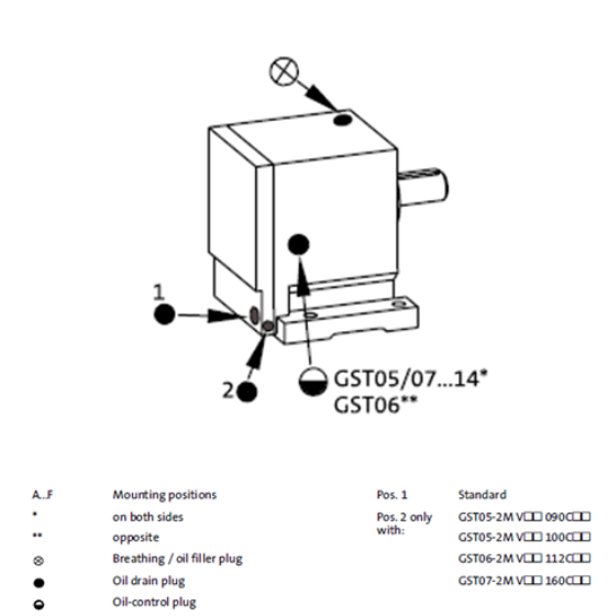
      Figure 3: GST gearbox lubrication service points (Source: Geared Motor Spares)
Figure 3 illustrates the various lubrication service points on a Lenze GST type gearbox (Geared Motor Spares).
To take an oil sample, we will employ the following procedure:
- Ensure that the gearbox/oil is at normal operating temperature.
- It is not safe to take a sample while the gearbox is in operation due to the proximity of hazardous moving parts. We will therefore instead stop the machine and take a sample as soon as the drive motor is safely isolated.
- 100ml will be extracted using a Vampire Pump and entering the gearbox through the Breathing/oil filler plug as displayed in Figure 3.
- This method of extraction is known as the Drop Tube Sampling Method.
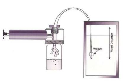
Figure 4: Drop Tube Sampling Method (Source: Zidoune)
Figure 4 shows a Vampire Pump extracting oil using the Drop Tube Sampling Method (Zidoune).
Precautions when sampling:
- Record time, date and operating conditions.
- Oil must be at operating temperature.
- Ensure clean bottles and new tubing are used.
- Take oil from middle of gearbox i.e. not too close to the bottom. A turbulent zone is best.
- Samples should be sent for laboratory testing without delay.
- Poor sampling = poor results = poor decisions (Zidoune, 2013).
3.3 Test Findings
Visual Inspection
This can be performed by onsite staff prior to laboratory analysis and observations will be aimed at the following:
- Foaming – an indication of contamination, passage through restricted openings or excessive churning.
- Emulsion – water has entered the gearbox.
- Darkening – oxidation has occurred or oil has been exposed to excessive heat.
Laboratory Analysis
On receiving laboratory results, we will consider the following factors in estimating the health of the gearbox:
- FTIR – This provides information about oil chemistry and particulates. It can also determine if there has been a decrease in desirable content such as corrosion inhibitors.
- Viscosity – This can tell us much about the lubricant’s condition. It can also give us an insight into system health when considered alongside factors such as detergency and dilution.
- Metal Concentration – This is a key health indicator. The presence of certain metals can point towards the defect location e.g. Lead and Tin detected in large amounts indicates wear of a white metal bearing.
- TAN/TBN – Acid number determines amount of oxidation present in the oil. Base number is an indication of the capacity to neutralise acids.
Fault Level Settings
- Gearbox or oil manufacturers should be consulted, however setting useful alarm limits can be subjective as there are many variables in the operating context that it is not possible to account for in their specifications.
- Alarm limits are best set by initially estimating, based on specifications, and then gathering data over a period of time to ‘tune’ the initial estimates. This will help reduce both false triggers and potential failures.
- As there are three CBWs in the wash house with identical drive systems, there is a likelihood that a gearbox will be fully overhauled in the not too distant future. We could use this opportunity to get data from perfectly healthy system i.e. a reconditioned gearbox with new oil.
ISO Coding
Sample Standard Cleanliness Target for an Industrial Gearbox: ISO 17/15/12 (Angeles, 2003)
Table 2

Table 2 contains hypotethical data that we would expect to see in an oil sample taken from a healty gearbox. Using ISO 4406 methods with this data would give us a code of 17/15/12.
3.4 Conclusion
Trending
It is imperative that a trend is developed from the successive analysis exercises. This will result in a graph curve which displays system health and allow for a timely maintenance intervention when required.
Recommended sampling frequency
- Care must be taken here as 100ml test amounts will render the gearbox empty of oil after 48 samples.
- Topping up the gearbox after each sample is not recommended as introducing new oil dilutes the existing content and thus distorts WDA data.
- Current oil replacement interval is every 4 years.
- Initial sampling frequency will be every 6 months with the gearbox oil level topped up every 12 months.
Quick wins
Spurlock (n.d.) states that one of the most common points of ingress for contamination in a gearbox is the OEM breather. It is recommended that an aftermarket breather be used instead.
4.1 Equipment Description
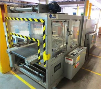
Figure 5: Novopac ANL 090 Wrapper (Source: Bidspotter)
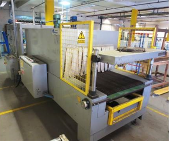
Figure 6: Novopac BM2009 Heat Shrinking Oven (Source: Bidspotter)
Figures 5 and 6 show examples of the Novopac Wrapper and Heat Shrinking Oven used in SGS (Bidspotter).
- Novopac ANL 090 Wrapper and BM2009 Heat Shrinking Oven (both function as a combined unit).
- Power: 41kW.
- Output per min.: 8/16 packs.
4.2 Testing Overview
It was decided that SGS would purchase a thermographic camera and have one of the maintenance technicians trained in its operation.
The supervisor consulted with the technician immediately after the study was completed and again when the full report was completed.
4.3 Test Findings
There were two areas that were cause for concern: the three phase power supply connection and the DIN rail mounted contactors.
Three Phase Power Supply Connection
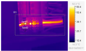
Figure 7: IR image
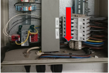
Figure 8: Standard image
Table 3
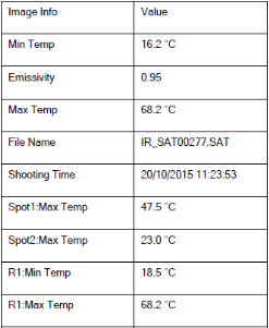
Figures 7 and 8 show both an IR and a standard image of the three phase connection block. Table 3 lists the data recorded by the camera in this instance.
Action taken: The hot spot found in Figure 7 was found to be a loose connection on the DIN rail connection block. Tightening the same connector resolved the issue.
DIN Rail Mounted Contactors
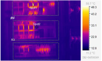
Figure 9: IR image
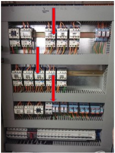
Figure 10: Standard image
Table 4
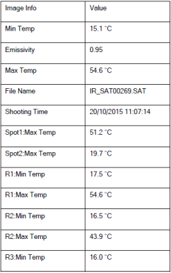
Figures 9 and 10 show both an IR and a standard image of the DIN rail mounted contactors. Table 4 lists the data recorded by the camera in this instance.
Action taken: Figure 9 indicates that there is a temperature build up between the contactors. On consulting previous reports, it was found that the temperature readings were similar during the last thermographic study. At this point the contactors were actually located closer together. A recommendation was made at that time to ‘space out’ the contactors to allow for extra cooling. However this has made no difference but since there has not been deterioration in the state of the contactors, SGS has decided not to take any further action at present.
4.4 Conclusion
The overall conclusion is that, beyond the tightening of the loose connection, there is no serious action required regarding repairs.
However SGS has realised that there are shortcomings in the testing procedures which are mainly down to the technician not being trained to the proper standard. Listed below are the observations and recommendations relating to this viewpoint:
- The approach being applied is a Qualitative one which is sufficient for identifying the presence of a fault. It is also effective as a comparative technique.
- A Qualitative approach measures the Blackbody Apparent Temperature. Neither reflected/transmitted radiation nor emissivity has been accounted for.
- To get a true temperature reading, a Quantitative approach would be required. This will not only identify the presence of a fault but also its severity.
- Reflected/transmitted radiation is accounted for by entering the ambient temperature in the IR Camera. This can be done using pre-measured or estimated values. A correct entry here would provide the Blackbody temperature.
- Emissivity can be accounted for by entering a pre-measured or library values. A correct entry here, combined with accounting for the reflected/transmitted radiation, would provide the actual temperature.
5.1 Equipment Description
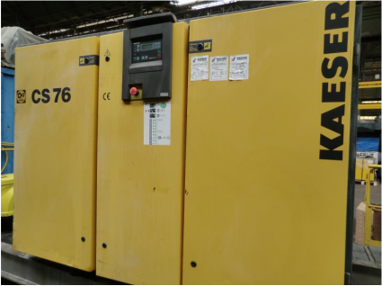
Figure 11: Kaeser CS76 (Source: Synairgies)
Figure 11 shows the type of Kaeser air compressor used in SGS (Synairgies).
- Kaeser CS76.
- Type: Rotary screw ‘wet’.
- Power: 45kW.
- Motor speed: 3000rpm.
- Mains frequency: 50Hz.
- Pressure: 7.5bar.
- Year of manufacture: 2004.
- Total running hours: 53563.
- On-load running hours: 42789.
- Recommended frequency for bearings replacement: 35000 hours – this activity has yet to be completed.
5.2 Testing Overview
The most likely cause of a screw compressor to fail is its bearings (KCF Technologies, n.d.).
Accelerometer Locations
- For our Kaeser machine, we will apply vibration monitoring at the radial bearing positions of both the motor and compressor.
- This area will get a particular focus because OEM specifications suggest the bearings should have already been replaced. SGS is hoping that vibration analysis will give a true indicator of bearing condition and thus inform of the optimum time for bearing change-out.
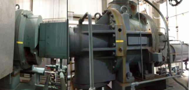
Figure 12: Sensor locations (Source: KCF Technologies)
Figure 12 shows typical mounting positions, in yellow, for sensors to measure vibration at motor and compressor radial bearings (KCF Technologies).
Mounting technique
- Accelerometers will be stud mounted to help ensure the most accurate readings.
Accelerometer selection and equipment set-up
- Frequencies associated with bearings usually occur in the 1 to 5 kHz range.
- For this application an accelerometer with 25 kHz natural frequency is required.
- Sampling frequency (fs) = 2.56 x 5000 = 12800 Hz.
- For Fast Fourier Transform Spectrum Analysis, to achieve a frequency resolution of less than 1Hz:
- df = fs/N ≤ 1
- N is the number of data points.
- N = 2^14 = 16,384
- fs/N = 0.78125
- Crest Factor or Kurtosis on Time Wave Form Acceleration signal can be employed to assist with diagnosis.
- Velocity and Acceleration will be the main focus for FFT.
5.3 Test Findings
TWF and FFT
For fault diagnosis, we will refer to TWF and FFT graphs.
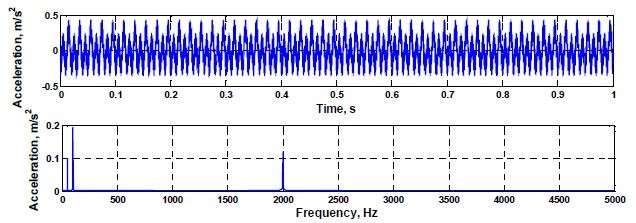
Figure 13: TWF and FFT (Source: Sinha)
Figure 13 displays vibration acceleration measurement for a ball bearing in the initial fault stage (Sinha).
Vibration Alarm and Fault level examples
Table 5 (Source: Zargar)
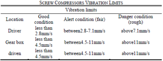
Table 5 lists vibration limits for a similar size and specification to the Kaeser CS76 (Zargar).
5.4 Conclusion
A successful vibration monitoring program can be most difficult to attain for screw compressors. This is because of the high frequencies associated with the bearings, gearbox, male and female rotors. The associated noise pollution of the compressor can cause additional monitoring problems (Zargar, 2013).
For the Kaeser compressor, there is a risk that bearing wear is present because of the hours run by the machine. However we cannot draw a firm conclusion on this until we develop a trend based on several sets of analysis data.
The ultimate goal is to capture the point at which the bearings begin to deteriorate and from there successfully monitor the P-F interval. This will enable a well-judged maintenance intervention.
CM ‘want to have’: If sufficient finance was available, a great option would be to invest in an Online monitoring system and have data fed back to a central PC. The software package could then issue periodic reports as well as alarm condition notifications.
It is clear, I believe, from this report that embarking on a Conditioning Monitoring programme would bring great benefit to SGS.
As well as the immediate gains to be made on the above equipment, the following should also result as pleasant ‘side effects’:
- An awareness will have developed among the key stakeholders of the advantages of CM over other types of maintenance.
- Technical staff will have an opportunity to upskill in either carrying out CM activities such as the Thermography study or be involved in interpreting results from Lubrication and Vibration analysis.
- There will be a willingness to roll out CM to other pieces of equipment. Thermography is an obvious contender as the equipment is already purchased.
- Downtime in the Wash House should be reduced as potential failures in the 18 Stage CBW drive gearbox will be identified before descending into functional failures. Again, as soon as this benefit is realised, this approach should carry across to other equipment.
- The criticality study which underpins the CM strategy will help focus technical resources on the most important equipment to the business.
- The expected success of the programme in the Cork plant should result in adoption of CM across the other sites in Ireland as there has always been close cooperation in terms of maintenance practices and parts sourcing.
- There will be an opportunity for the maintenance department to come to the forefront of the company when reporting the expected good news stories to emerge from adopting this new maintenance approach.
- Continuous improvement will organically develop from CM and bring kudos to the maintenance team.
- The general non-contact nature of CM will enhance safe working practices.
- The non-intrusive nature of CM will result in less equipment stoppages and reduced maintenance induced failures.
- The maintenance team will be encouraged to work more closely with equipment and components suppliers. This will help better inform future selection of machinery.
- It should be the beginning of a new maintenance culture across the organisation.
Angeles, R. (2003). Tables on Oil Analysis. [Online]. Available from [Accessed 12 November 2016].
Bidspotter (n.d.). Impianti Novo Pac heat shrink-wrap tunnel.[Online]. Available from [Accessed 08 November 2016].
Geared Motor Spares (n.d.). Lenze GST Geared Motors.[Online]. Available from [Accessed 08 November 2016].
Geared Motor Spares (n.d.). L-force Geared Motors.[Online]. Available from [Accessed 11 November 2016].
KCF Technologies (n.d.). Vibration Monitoring of Compressors. [Online]. Available from [Accessed 16 November 2016].
Pruftechnik (2002). An Engineers Guide to Shaft Alignment, Vibration Analysis, Dynamic Balancing & Wear Debris Analysis. [Online]. Available from [Accessed 13 November 2016].
Sinha, J. (2016). PG Course in Reliability Engineering and Asset Management, Unit M04:
Condition Monitoring. School of Mechanical Aerospace and Civil Engineering. University of Manchester.
Spurlock, M. (n.d.). Reducing Gearbox Oil Contamination Levels. [Online]. Available from [Accessed 11 November 2016].
Synairgies (n.d.).Synairgies – Compresseurs Doccasion.[Online]. Available from
[Accessed 08 November 2016].
Zargar, O. A. (2013). Hydraulic Unbalance in Oil Injected Twin Rotary Screw Compressor Vibration Analysis. [Online]. Available from
[Accessed 17 November 2016].
Zidoune, M. (2013). Lubricants Handling and Analysis. [Online]. Available from [Accessed 11 November 2016].
Wheelhouse, P. (2014). Exercise 3_5 Criticality, Unit M01: Asset Management & Maintenance Strategy. School of Mechanical Aerospace and Civil Engineering. University of Manchester.
Â
8.1 Appendix A
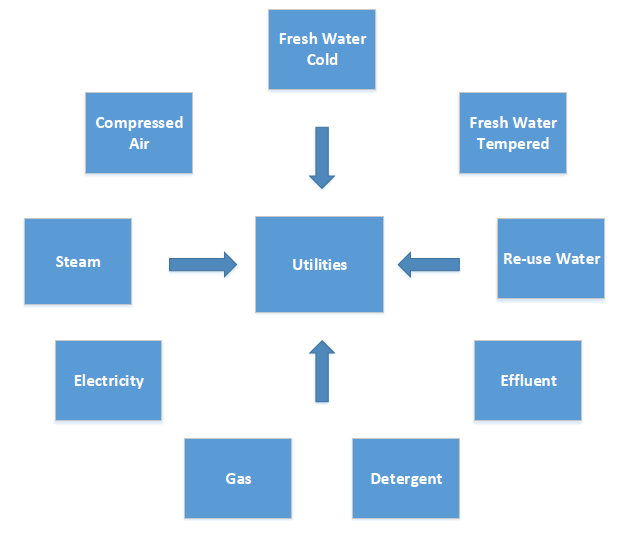
Figure 14: SGS Utilities Systems
Figure 14 shows the systems which form Utilities at SGS.
8.2 Appendix B
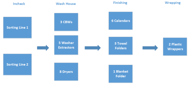
Figure 15: SGS Process System/Equipment
Figure 15 shows a high level view of process systems and equipment at SGS.
8.3 Appendix C
Criticality Scoring Scheme(Wheelhouse, 2014)
The plant has decided on a criticality scoring scheme which consists of four different factors which will be multiplied together to give an overall score for equipment criticality. These factors are: Redundancy, Failure Likelihood, Failure Duration & Financial Impact. A scoring scheme has been devised for each factor as follows:
Redundancy = Number of units required / Number of units available
Likelihood
KeywordEvents per YearScore
Never00
Very unlikely                 <0.11
Unlikely   0.2 – 0.6          2
Probable   1.0 – 1.5          3
Almost certain        >24
Duration
KeywordScore
Hours1
Days2
Weeks3
Months4
Financial Impact
KeywordScore
Repair cost only1
Additional cost penalty2
Potential loss of sales3
Immediate loss of sales4
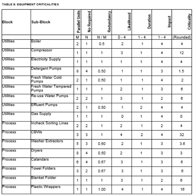
Table 6 lists equipment criticalities as calculated at SGS.
Angeles, R. (2003). Tables on Oil Analysis. [Online]. Available from [Accessed 12 November 2016].
British Standards Institution (1999). BS ISO4406:1999. Hydraulic fluid power –
Fluids – Method for coding the level of contamination by solid particles. Published under the authority of the Standards Committee.
Felten, D. (2003). Understanding Bearing Vibration Frequencies. [Online]. Available from [Accessed 16 November 2016].
Geared Motor Spares (n.d.). L-force Geared Motors.[Online]. Available from [Accessed 11 November 2016].
KCF Technologies (n.d.). Vibration Monitoring of Compressors. [Online]. Available from [Accessed 16 November 2016].
Moubray, J. (1991). Reliability-centered Maintenance. Butterworth-Heinemann Ltd.
Navarro, D. et al (2005). Industrial Lubrication & Oil Analysis Reference Guide. [Online]. Available from [Accessed 12 November 2016].
Pruftechnik (2002). An Engineers Guide to Shaft Alignment, Vibration Analysis, Dynamic Balancing & Wear Debris Analysis [Online]. Available from [Accessed 13 November 2016].
Smith, Donald R. (2011). Pulsation, Vibration, and Noise Issues with Wet and Dry Screw Compressors. [Online]. Available from [Accessed 16 November 2016].
Spurlock, M. (n.d.). Reducing Gearbox Oil Contamination Levels. [Online]. Available from [Accessed 11 November 2016].
Terry Clausing, L. (n.d.).Emissivity:Understanding the difference between apparent and actual infrared temperatures. [Online]. Available from
[Accessed 10 November 2016].
Zargar, O. A. (2013). Hydraulic Unbalance in Oil Injected Twin Rotary Screw Compressor Vibration Analysis. [Online]. Available from
[Accessed 17 November 2016].
Zidoune, M. (2013). Lubricants Handling and Analysis. [Online]. Available from [Accessed 11 November 2016].