Design of high Speed Machines with Low Loss Materials
|
PROJECT TITLE |
||||||||||||||||||||||||||||||||||||||||||||||||||||||||||||||||||||||||||||||||||||||||||||||||||||
|
Design of high Speed Machines with Low Loss Materials |
||||||||||||||||||||||||||||||||||||||||||||||||||||||||||||||||||||||||||||||||||||||||||||||||||||
|
RESEARCH SUMMARY |
||||||||||||||||||||||||||||||||||||||||||||||||||||||||||||||||||||||||||||||||||||||||||||||||||||
|
Nowadays high-speed machines are researched for use in many sectors for application in gas turbine engines, high speed fly wheels, turbo chargers, electrical vehicles, CNC machines [] etc. In the design of high-speed machines, the magnetic properties play an important role, the use multiple types of magnetic materials to shape the required effective magnetic characteristics has not been extensively studies to date. Mixed magnetic material core (MMMC), can deal with high frequencies as well as thermal aspect together, that has added a new dimension in the high-speed machine for performance issue. MMM core, is combined with the essential unites of soft magnetic materials contain with a magnetic property are proposed, and their characterisation analysis and design procedure are studied in this study. The analytical process for this material and its physical attributes are also studied in this research. |
||||||||||||||||||||||||||||||||||||||||||||||||||||||||||||||||||||||||||||||||||||||||||||||||||||
|
RESEARCH PROPOSAL |
||||||||||||||||||||||||||||||||||||||||||||||||||||||||||||||||||||||||||||||||||||||||||||||||||||
|
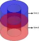
Current progresses in material technology have introduced new types of magnetic materials such as Nickel-iron, Silicon-iron, Cobalt-iron, Nano crystalline metals, amorphous etc. Now a days, these material are being used in many applications such as in high speed machines. Conversely, those metals usually have low mechanical strength and are found to be fragile. To making magnetic devices with new magnetic materials, a mechanically strong structure has been strengthened. One option is to incorporate core Material such as Si-steel or ferrite sandwiched together with the brittle material resulting in a MMMC. In this research, the process applicable for the design and analysis of MMMCis studied. A MMMCmay consist two or more Materials are in a magnetically parallel arrangement. To analyse this type of core, 3D simulations are required.The basic case of two core Materials in parallel is shown in Fig. 1.Homogenization approaches for laminated magnetic cores have been considered in the past[]. New iron-resin compositematerials for soft magnetic have been applied in[]. The research investigates a SMC homogenizationstrategy and different mixing rules [] such, Vigot, Lichtenecker logarithmic, Maxwell-Garnett, Rayleigh equation, Lewis-Nielsen. These mixture rulesare compared in the research.3D simulations of a magnetic core comprising of Nanocrystalline soft magnetic Fe-M-B (M = Zr, Hf, Nb) Material (core-1) and toroidal ferrite core (core-2) is developed to validate thehomogenization strategy. The mixtures rules have been applied to the core and the equivalentMaterial properties have been used with in a 2D simulation. The validation is carried out by comparing 2D, 3Dresults. Through the two dimensional (2D) procedure we are able to achieve input-output voltage and equivalent loss results to those computed by three dimensional (3D) simulations. Experimental comparison in also performed for the two core arrangement. The results obtained from the 3D model and experiments are found to offer comparable results with the 2D model with the different mixture rules.
Fig.1 Parallel arrangement of MMMC The research work intended to be carried out in related to following aspects: (i) Characterization of MMMC (ii) mixture rules for MMMC and losses mixing strategy(iii)Modelling a high speed machine with having MMMC.(iv)Investigate thermal and vibration aspects.These aspects will be investigated under this research project. The literature review provides a brief overview of the literature available and the knowledge gaps in the literature. We have selected four main challenges of the MMMC in high speed machine and formulated the corresponding research question for each: Research Question 1: How to effectively evaluate hysteresis loops of MMMC and evaluates the structural integrity of core material under stresses? Under this research question, we will investigate the soft magnetic material characteristics for high speed machine. The investigation will be conducted under different applications:The first application is to investigate the core materials parameters required for the 3D-2D modelling with FEM.The second application is to develop a laboratory test bed to determine Hysteresis Loops of MMMC.The laboratory test would include the average BH curve for each core and investigate the material validation. Research Question 2: How to evaluate the mixture rules of cores and compare equivalentmaterial propertied with in 2D simulation and effectively evaluate high frequency total core losses and investigateloss mixing strategy? Under this research question, we will investigate the mixture rules of MMMC. The investigation will be conducted under different applications: The first application is to investigate themixturerulesand equivalent Material propertiesfor FEM simulation. The validation of mixture rules is carried out by comparing 2D, 3D FEM results.The second application is to develop a laboratory test bed to determine total core losses of MMMC under various frequency ranges and investigate loss mixing strategy for MMMC. Research Question 3:How to model effectivelya high speed machine with having MMMC and evaluate gear aspect in high speed machine for high power density? Under this research question, we will propose a model of high speedmachine with MMMC. The investigation will be conducted under two different applications:The first application is to investigate the high speed machine behaviour by analysing in FEM method. The FEM analyse will include the machine performance, gear aspect in high speed machine and results comparison. The second application is to make high speed machine prototype for practical analysis and develop a laboratory test bed to determine machine performance. Research Question 4: How to effectively investigate thermal and vibration aspects in high speed machine? Under this research question, we will investigate high speedmachines thermal and vibration aspect. The investigation will be conducted under two different applications:The first application is to investigate the temperature characteristic in high speed machine. The temperature characteristic would include lumped parameter thermal model and FEM analysis. The second application isto investigate the design of the machine model to estimate vibration effect.The vibration has direct impact on the electrical properties in the process of electricity conversion. After the core is magnetized, vibration is caused by magneto-electric. It is well known that,the magnetic gear (MG), deals with major benefits to reduced noise, lowest vibration, enhanced reliability, overload protection, and physical isolation between the input and output shafts.The machine design optimization and FEM method will be investigated under this application. This research study is planned to address above research questions by following both experimental and software simulations on laboratory scale hardware platform. |
||||||||||||||||||||||||||||||||||||||||||||||||||||||||||||||||||||||||||||||||||||||||||||||||||||
|
LITERATURE REVIEW |
||||||||||||||||||||||||||||||||||||||||||||||||||||||||||||||||||||||||||||||||||||||||||||||||||||
|
There are several research studies conducted on high speed machine design. Perhaps, number of studies has been conducted on developing electric motors by using SMC core due to excessive eddy current losses.High speed machines are considered by rated speed in the ranges of 10 krpm to over 200 krpm. They have been used for long time due to their advantages, among which high power density, high efficiency, reduced size, weight and costs. High speed electrical machines are being utilised on an increasing scale day by day, mainly to increase the output power density, torque of electrical machines.Recently, the author of[] studied the characteristic of soft magnetic materials on the high-speed machine design . The soft magnetic composite (SMCs) possesses many unique properties and its application in electrical machines has undergone significant development in the past two decades [, , ]. There are several research studies conducted on SMCs to improve the high speed machine performance.The author of [] studied design considerations of an electric motor with soft magnetic composite cores. A researcher of []has experience with using soft magnetic composites for various electrical machines such as axial field brushless dc machine, reluctance machines, induction motors, permanent magnet machines, radial + axial field permanent magnet motor, claw pole armature machines, permanent magnet servo drives and so on. The authors of [] have introduced SMC Material for a PMDM (Permanent Magnet Disk Motor) application, which decreases iron losses and leads to an overall efficiency improvement in EV(electric vehicle) drive application. Soft magnetic material has been playing an important role for many years to develop machine performance and reduce costs. Soft magnetic Material status and trends in electric machines have been discussed in[]. Due to low mechanical strength of SMC the authors of [] have proposed the combination of hard ferrite magnets and soft magnetic composites in an axial flux machine in terms of costs improvement and increase high efficiency. Various types of motor prototypes have been developed based on SMC cores by using solid core and lamination steel together bydifferent researchers, such as induction motor [14], transverse flux motor [, , ], claw pole motors [], axial field motor [, ]. The other advantages of SMC include low eddy current loss as the iron particle is insulated by coating. SMC also have a significantly greater total loss than electrical steels at low frequencies in []. Other aspects,a researcher of []have introduced loss coefficient characterisation for high frequency in electrical machine applications. The loss characterization of this machine has involved up to 4 kHz. The authors of[, ] and []have been used Epstein frame for core loss characterization at high frequency up to 6kHz. The authors of[]have been used SMC cores to Reduce Iron Losses within 1 KHz frequencies range. Significant challenges exist in the implementation of high speed electrical machines with soft magnetic material. The most important issues are the much higher losses per volume, thermal and vibration aspect as well as several structural concerns[, ].Specifically,high speed machine design constraints outlined in TABLE 1. TABLE 1High Speed machine Design Requirements
During last decades different types of magnetic materials have beenused including pure iron and its alloys, such as Fe-Ni, Fe-Ni-P, Fe-Nd-B and Fe-Siand soft and hard ferrites, such as Ni-Zn, Mn-Zn and Baferrites.New materials including amorphous materials, amorphous wires, nanocrystallinematerials and today’s soft magnetic composite materials are the latest development in magnetic history [, ]. The idea of using composites for soft magnetic application is not new. It appeared more than 100 years ago, iron -resin and Fe-Ni composites have been rarely used because of their properties e.g. magnetic permeability, mechanical strength[, ]. However, for these kinds of materials limitations have being overcome with the development of new shaping technologies. Recently these composites find surge use in electrical machines.Since, MMMChave brittle, low mechanical strength and are not sintered,authors of [] used of stress relief to the temperature limit set by coating can be reached by using binder like LB1 additives for boost up MMMC materials strength for electric machine. In particular, the Ni3Fe particles with a polymer binder produces composite materials and trodden into toroid shape[]. Thermal analysis is another important concern of machine design, especially for high speed machine. A number of studies have been conducted on developing thermal effect in high speed machine. The authors of [] studied a high speed generator using lumped parameter thermal modelling to acquire the average temperature of different parts of motor, the authors of [] used FEA method to calculate the temperature distribution of a high speed synchronous reluctance machine, however the rotational core loss was not included. The computation of the core loss and thermal behaviour of high speed SMCmotor has been discussed []. The vibration effect is another challenge to design a high speed machine. There is several research studies conducted on vibration effects of high speed machine[]. The magneto-mechanical vibrations and audible noises under different core bending structures have been studied [].In [], the audible noises of transformer are generated by core vibrations owing to magnetostriction and magnetic forces. In these investigations, silicon steel material with a highly oriented SiFe composition is considered. The authors of [] studied that magneto striction in non-oriented electrical steel is primary source of vibrations and acoustic noises in electrical machines. In counter to the vibration effect gears aspect is widely used in high speed machine. Gears and gearboxes are broadlyapplied for torque transmission and speed control in high speed machine.Through the mechanical gear has a high torque density;however it arises some integral problems such as heatand noise, whereas vibration is ofmajor issues.In opposite to the magnetic gear (MG), it’sdealwith majorbenefitsto reduced noise, lowest vibration, enhanced reliability, overload protection, and physical isolation between the input and output shafts. Conversely, MGs have received pretty little attention for a long time, because of the poor torque density and relative complexity of the magnetic circuits[, ]. The knowledge of MGs has been familiarized in the beginning of the 20th century. In early 1913, a US Patent Application introduced an electromagnetic gearing topology[], howeverat that time, almost no one was interested in it. Until, in 1941, the author of [] has introduced a MG topology, which was quite similar to a mechanical spur gear and people slowly paid attention to MGs. Due to the poor performance of ferrite permanent magnets material people are not widely used in industrial fields. Until, in the 1980s the high-performance neodymium iron born (NdFeB) PM material was developed, the research on MGsawakened great interests again. Although various converted magnetic gear have been delineated, it is important to make a comparison with the mechanical gear. Table 2 summarizes the MGs and compares them with a mechanical spur gear, with emphasis on the torque density and gear ratio. It is seen that all MGs (except the planetary type MG and coaxial magnetic gear) have low torque density, which is far less than that provided by the mechanical spur gear. Planetary type MG has high torque density compare of other types. Which has 35 kW permanent magnet motor with a base speed of 4000 rpm and is integrated into a permanent magnetic gear with a gearing ratio of 8.67 []. The unit is unique in the sense that it has high torque density of 130 kNm/m3. On the other hand coaxial magnetic gear has also high torque density of 108.2 kNm/m3, high speed and 4.25:1 gear ratio. This is similar with concentric magnetic gear ratio. Besides this, magnetic worm gear and skew gear has low torque density but magnetic worm gear has high gear ratio, which to be used in case of mechanical power transmission []. Furthermore, magnetic skew gear has low torque density 0.15kNm/m3, which is far less than that provided by the conventional external magnetic gear []. Such low torque density seriously limits their popularization and application. In addition, although the concentric magnetic gear [] and coaxial MG [] have a high torque density, the former cannot achieve variable speed driving, while the latter has a low utilization of PMs. The multi element magnetic gear presented in [] was reported to be disappointing in its performance at speed of 140 rpm in terms of efficiency and gear ratio of 24:1. In addition, the low-speed performance described indicated severe restrictions on its use as a torque-transmitting device. Such a gear would have built-in protection from overload, and could also be arranged to be free from backlash []. TABLE 2 Comparison Between Mechanical spur gear vs. Magnetic gear
Above approaches consider that using magnetic geared MMMC with permanent magnet high speed machine can offer significant advantages for application to electric vehicles, and electric ship propulsion [, ]. |
||||||||||||||||||||||||||||||||||||||||||||||||||||||||||||||||||||||||||||||||||||||||||||||||||||
|
RATIONALE FOR THE RESEARCH |
||||||||||||||||||||||||||||||||||||||||||||||||||||||||||||||||||||||||||||||||||||||||||||||||||||
|
The literature provides significant research studies conducted on different aspect of the MMMC in high speed magnetic gear machine. At the present time, in high speed machine the magnetic properties has taken a essential responsibility to increase its performance. High speed machines are characterized by rated speed and rated watts to hundreds of kilowatts. They have been used for long time due to their advantages, among which high power density, reduced size, weight and costs. High speed electrical machines are being utilised on an increasing scale day by day, mainly to increase the output power density, lower losses and torque of electrical machines.Through the mechanical gear has a high torque density; however it arises some integral problems such as heat and noise, whereas vibration is of major issues. In opposite to the magnetic gear (MG) deals with major benefits to reduced noise, lowest vibration, enhanced reliability, overload protection, and physical isolation between the input and output shafts. In this research MMMC has been proposed for high speed MG machine and their characterisation, design and analysis are studied |
|
RESEARCH METHODOLOGY |
||||||||||||||||||
|
In order to accomplish the research goals in an efficient manner a modified version of the generic research methodology in [] will be followed, however this methodology does not give an insight details of how to conduct the actual investigation. Accordingly, we will illustrate the investigation methodology for each key research problem separately. The generic research Methodology consists of:
The approach and research methodology are followed for all the RQ started in the previous section. Investigation Methodology of RQ1 : Figure 2 shows the investigation methodology that we adopt for addressing RQ1. As can be seen from the figure, we consider two approaches, simulation- based and practical-based. In simulation-based approach, we first select core materials. Then we investigate proposed core parameters and implemented by designing model for FEM 3D simulation. In Practical measurement based approach, we select the same core model as we choose in the simulation based approach. Then we plan the measurement experiment which includes selection of measurement instruments, procedure etc. We then conduct the experiment and collect the results and post-process the results from MATLAB programming. After the post processing the resulting average BH curve from practical approach, has been used in 3D simulation for investigate the material validation.
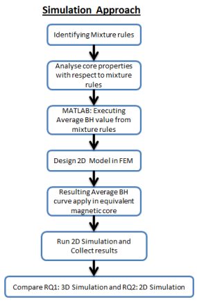
Figure 2 Investigation Methodology of RQ1 Investigation Methodology of RQ2 : It is important to note that there are little research has been conducted with mixture rules for MMMC. This research question investigates a SMC homogenization strategy and different mixing rules [7]. Figure 3 and Figure 4 shows the investigation methodology that will be followed to address RQ2. As can be seen from the figure 3, we follow one approach, simulation based approach to validate the equivalent core material. Initially, we identify the mixture rules from literature review. We then analyse the magnetic properties for each core. Then we execute best mixture rules from MATLAB code by comparing average BH curve. The resulting mixture rule was used in equivalent magnetic core as a material property in 2D FEM simulation. After simulation, the validation is carried out by comparing 2D, 3D results.
Figure 3Investigation Methodology of RQ2
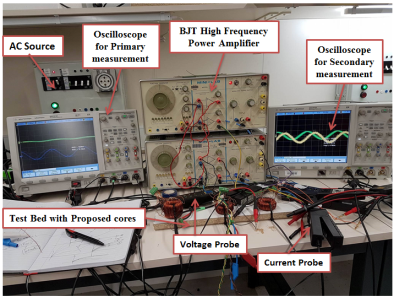
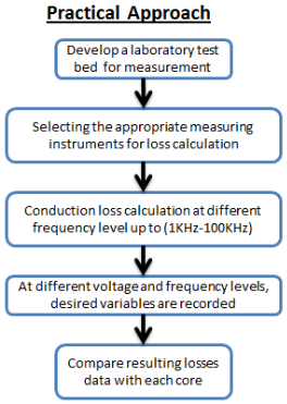
Figure 4Investigation High Frequency core loss As can be seen from the figure 4, we consider thepractical approach. In apractical approach, 1st we develop the laboratory test bed for the measurement. Then we plan the measurement experiment which includes aselection of measurement instruments (BJT Power amplifier, Oscilloscopes, Current probes, voltage probes, USB), procedure, etc. Then we conduct the experiment. First, a frequency value is chosen for the test, and signal generator is setto that value. Before the test began, the amplifier gain needs to be normalized according to material behaviour. Next, at different voltage levels, desired variables are recorded. This procedure is repeated at several frequencies (1khz to 100khz). Then resulting losses are then compared with the other material core losses. The mixture rulesarealso investigated for losses. Investigation Methodology of RQ3: Figure 5 shows the investigation methodology that we adopt for addressing RQ3. As can be seen from the figure, 1st we will develop a high speed MGs, machine design model with MMMC. Then we will investigate proposed design model and then we will implement by developing amodel for FEM 3D simulation. Then we will conduct the simulationanalysis and justify the simulation results based on power density, efficiency, speed, and power, losses, temperature and vibration aspect. Then we willpropose, a prototype model based on simulation results. Next, we will develop the laboratory test bed for the measurement. Then, the experimentresults will compare with the 3D FEM simulation.
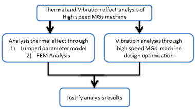
Figure 5Investigation Methodology of RQ3 Investigation Methodology of RQ4: Figure 6 shows the investigation methodology that we adopt for addressing RQ4. As can be seen from the figure, 1st we will analysis thermal and vibration effect of high speed MGs machine. Then we will investigate the thermal effect through the lumped parameters thermal modelling to get the average temperature of the different parts of the machine and another aspect we will consider for thermal analysis is FEA method.Then we will conduct the vibration effects investigation in high speed MGs (HSMGs) machine. The vibration has direct impact on the electrical properties in the process of electricity conversion. After the core is magnetized, vibration is caused by magneto-electric. It is well known that, the magnetic gear (MG) offers significant advantages of reduced acoustic noise, minimum vibration effects. The machine design optimization and FEM method will be investigated under this application.
Figure 6Investigation Methodology of RQ4 |


|
Step No. |
Title of Activity |
Activity Description and Relation to Research Questions |
||||||||||||||||
|
1 |
Literature review |
Extensive literature study on wide area high speed machine,soft magnetic composite (SMC) Materialand Magnetic gear to identify the research gap and questions. |
||||||||||||||||
|
2 |
RQ1,Characterization of MMMC |
Focused literature study on MMMC Material and the investigate the material characteristic for high speed machine |
||||||||||||||||
|
3 |
RQ2, Investigate mixture rules of core |
Investigate mixture rules of MMMC |
||||||||||||||||
|
4 |
RQ2, Analysis losses mixing strategy |
Determine total core losses of MMMC under various frequency ranges and investigate loss mixing strategy for MMMC. |
||||||||||||||||
|
5 |
RQ1/ RQ2Publishing and Reporting |
We publish and report our findings in reputed journal and conferences. |
||||||||||||||||
|
6 |
RQ3, Designa High speed MGsmachine model |
In this activity, we will design a high speed MGs machine design model with MMMC and analysis in FEM 3D simulation. |
||||||||||||||||
|
7 |
RQ3, Validate Performance |
In this activity, we will build prototype model based on simulation results. We will develop the laboratory test bed for the measurement. Then experiment results will compare with the 3D FEM simulation. |
||||||||||||||||
|
8 |
RQ1/ RQ2/ RQ3 Publishing and Reporting |
We publish and report our findings in reputed journal and conferences. |
||||||||||||||||
|
9 |
RQ4, Thermal and vibration effect |
In this activity, we will perform various technique to minimize thermaland vibration effects. |
||||||||||||||||
|
10 |
RQ4Publishing and Reporting |
We publish and report our findings in reputed journal and conferences. |
||||||||||||||||
|
11 |
Dissertation |
In this activity, the findings of all the research questions are reported in the form of the thesis accommodating the feedback received from reviewers during publications. |
||||||||||||||||
|
RESEARCH TIME LINESGantt Chart showing shaded time lines. If transferring from Masters to PhD please indicate the time lines already achieved. |
||||||||||||||||||
|
Title of Activity |
Timeline |
|||||||||||||||||
|
Y1 |
Y2 |
Y3 |
||||||||||||||||
|
1 |
2 |
3 |
4 |
5 |
6 |
7 |
8 |
9 |
10 |
11 |
12 |
13 |
14 |
|||||
|
||||||||||||||||||
|
||||||||||||||||||
|
||||||||||||||||||
|
||||||||||||||||||
|
||||||||||||||||||
|
||||||||||||||||||
|
||||||||||||||||||
|
||||||||||||||||||
|
||||||||||||||||||
|
||||||||||||||||||
|
||||||||||||||||||
|
RESEARCH COMPLETED TO DATE Provide a brief description of the components of your research project that you have completed. |
||||||||||||||||||
|
The research conducted till the date of writing this document listed in this section. Journal publications : Conference proceeding : Extensive literature review in Step 1 has been done. The literature review will be an ongoing activity throughout my candidature since it will keep me up to date with the current body of knowledge and state of art technologies in my area of research. More than seventy papers from reputed journals and conferences have been studied and summarised for this literature review. The Gantt Chart above shows the tasks that I completed in green colour and the pendingtasks in red colour and the ongoing tasks in yellow colour. Below is a brief summary of the work I have completed to date: Research under RQ1:
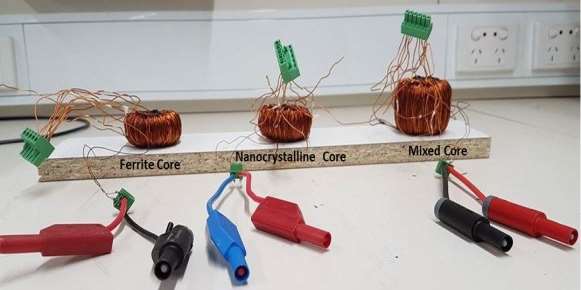
Figure 5 Experimental Setup
Fig.6 Zoom View of Test bed with proposed Cores
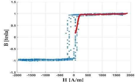
Experimental BH curves for Core 1
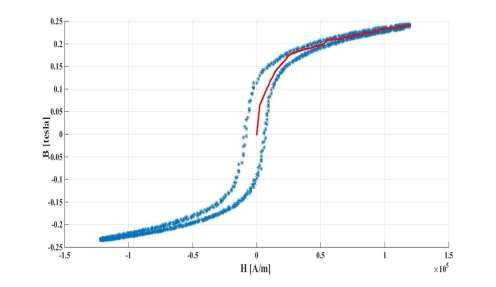
Experimental BH curves for Core 2
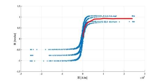
Experimental BH curves for Mixed core Research under RQ2:
Where, µ is the magnetic permeability of MMMC, µF and µN are magnetic permeability of ferrite core and nanocrystalline core respectively, ɸ is the volume fraction of the ferrite core, and ɸm is the maximum packing volume fraction of nanocrystalline.
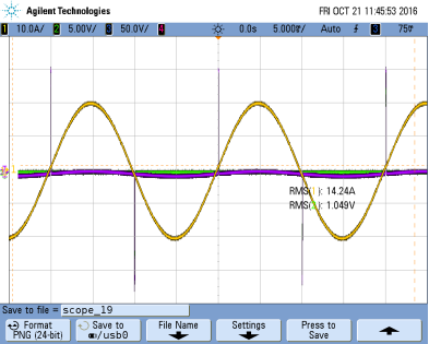
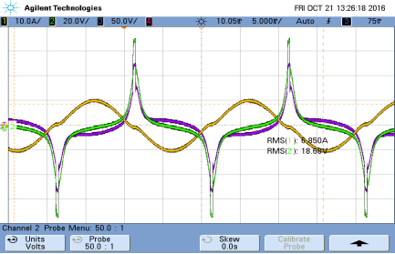
Core 1: Experimental Current (A)
Core 1: Experimental Voltage (V)
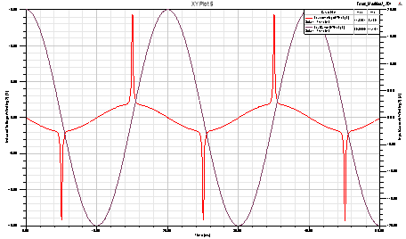
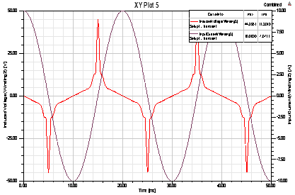
Core 1: 2D Primary and Secondary Voltage Simulation
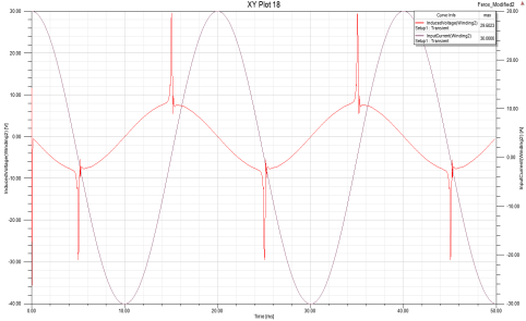
Core 1: 3D Primary and Secondary Voltage Simulation
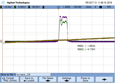
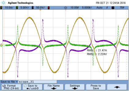
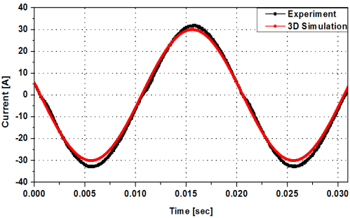
Core 2: Experiment
Core 2: 2D Simulation
Core 2: 3D Simulation
Core 2: 2D Simulation & Experiment Comparison
Core 2: 3D Simulation & Experiment Comparison
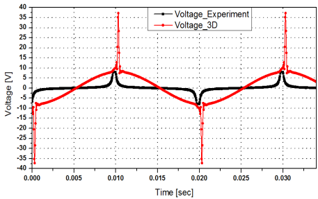
Core 2: 2D Voltage Simulation & Experiment Comparison
Core 2: 3D Voltage Simulation & Experiment Comparison
Mixed core Experimental Voltage and Current
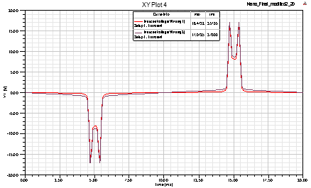
Mixed core 2D Simulation
Mixed core Voltage and current Comparison
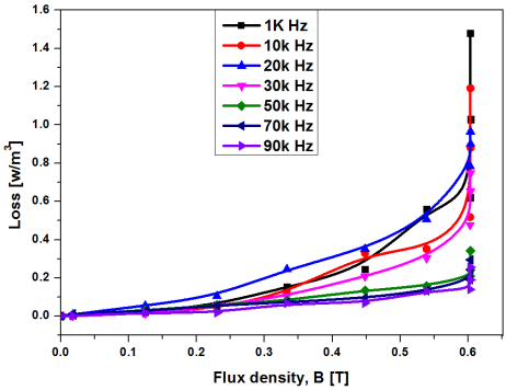
Experimental test bed for high frequencies core losses
|
||||||||||||||||||
|
SUPERVISOR COMMENTS, IF ANY |
||||||||||||||||||
|
MAJOR REFERENCES |
||||||||||||||||||