Engineering Systems and Components of Centrifuge
Â
Description
The main job of the horizontal decanter centrifuge is to separate materials of different densities. In this system, the centrifuge is required to separate the olive oil from water and any other solids such as stones.
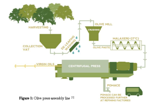 The decanter centrifuge (Figure 1) is part of the olive presser’s assembly line made up of four main machines: de-leafing washing, olive crushing mill, horizontal malaxer, and the centrifuge. Figure 1 shows briefly what the assembly line consists of.
The inputs into the centrifuge are olives which have undergone a number of processes through the other main machines of the olive presser assembly line. These processed olives are referred to as cake. This cake is the input of the decanter centrifuge and contains stone, water, other chemical additives, and oil.
The centrifuge uses the concept of sedimentation to separate the cake into ‘heavy’ liquid and ‘light’ liquid, the ‘lighter’ liquid being the olive oil, which is the output required from the system. Basically, due to the difference in densities the cake and oil will separate naturally given enough time (the oil floats on top of the cake). The centrifuge speeds up this process using high rotational speeds, exerting up to 4000G on the cake. This is useful since a process that would take hours to achieve could happen in a matter of seconds. The centrifuge rotates at high speeds, resulting in the separation of the contents inside the centrifuge according to their density, allowing the olive oil to be retrieved from the system [1].
ADD SCREENSHOT OF CENTRIFUGE
Overview of Operation
The cake is input to the system through a small inlet tube encased in a wider shaft. This shaft has an Archimedean spiral, i.e. the scroll, welded to it. The shaft together with the scroll is called the conveyor, and it is encased in a drum. The shaft, and thus also the scroll is turned by a motor & pulley system. The cake flows into the scroll area where separation of the olive oil from the cake occurs due to the high G’s generated by rotation and the angle at one end of the scroll. The olive oil and waste are output through nozzles at opposite ends of the centrifuge drum.
The centrifuge is attached to the frame using a pillow block bearing. The frame supports the entirety of the system.
Basic Sizing & Requirements
By comparing to existing centrifuges, the optimal drum diameter and rotational speed are 425 mm, and 3800 RPM respectively. A 1:4 design ratio (drum diameter compared to the drum length) is adopted, resulting in a centrifuge length of 1700 mm [2]. A beach angle of 200 is taken, as explained in Appendix 1.
Specification Sheet
|
Centrifuge Specifications |
|
|
Centrifuge Type |
Two-phase; Horizontal |
|
Maximum Overall Length |
3 m |
|
Maximum Overall Width |
1.5 m |
|
Maximum Overall Height |
1.5 m |
|
Input Rate |
450 kg/h |
|
Centrifuge RPM |
3800 |
|
Centrifuge Beach Angle |
200 |
|
Centrifuge drum diameter |
425 mm |
|
Centrifuge diameter to length ratio |
1:4 |
|
Centrifuge Length |
1700 mm |
|
Centrifuge shaft outer diameter |
120 mm |
Tree Diagram
The following tree diagram is a graphical representation of the centrifuge and its sub-systems. Please turn over to find the above mentioned tree diagram.
Block Diagram
The following block diagram is a graphical representation of how the centrifuge works in order to extract the oil from the olives. This graphical representation will provide a better understanding of how the sub-systems interact with one another. Please turn over for the above mentioned block diagram.
Â
Brief explanation of the chosen components
 Drive Frame (Figure 2): A tray to which the motor is bolted down to stay in position. It is attached to the legs of the centrifuge lower casing. It determines the distance between the shaft of the motor and shaft of the centrifuge.
Figure 2: Drive Frame
Centrifuge Frame (Figure 3): The overall frame of the decanter, this supports the entire structure of the centrifuge.
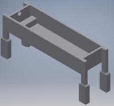
Figure 3: Centrifuge Frame
Upper Casing (Figure 4): The Upper casing covers the drum of the centrifuge. It blocks contaminants from making contact with the drum and restricts the user of the machine from making contact with moving parts, providing better safety.
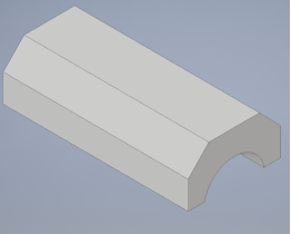
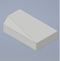
Figure 4: Upper Casing
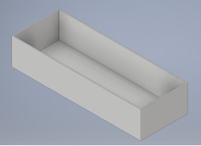 Lower Casing (Figure 5): The lower casing acts as a collector for the products discharged from the rotating assembly and transports them to receivers for onward handling. The casing has to keep these separated entities apart. So it can be concluded that the casing as an oil collector at one end and a cake discharge collector at the conical side.
Figure 5: Lower Casing
Feed Tube (Figure 6): A tube that the cake is transported to the centrifuge from the malaxer. This is also the input of the centrifuge. Its inner diameter is determined by its required input flow rate.
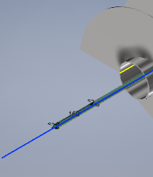
Figure 6: Feed Tube
3-phase Motor (Figure 7): The motor provides the initial torque required to rotate the belt. The motor chosen is the AEG AM 132M ZA4*[3], a 3-phase motor which provides 7.5kW of power, with the possibility of increasing the power up to 9.2kW through a small modification, making this a flexible choice.
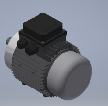
Figure 7: 3-Phase Motor
Belt (Figure 8): The Flat belt connects the pulley of the 3-phase motor and the centrifuge drum together, transferring power. The chosen Flat-belt is a Polyamide A-3c belt since it provides the appropriate thickness, allowable tension, and coefficient of friction, while also being appropriate for the minimum pulley diameter.
Pulley (Figure 8): The pulley is used to modify the speed of the drum and is connected to the motor.
Key: A 8 x 10 mm rectangular key 70 mm long is added to the motor pulley in order to make sure that the pulley spins together with the motor shaft in such a way that there is no relative motion between the two.

Figure 8: Belt and Pulley
Belt Guard (Figure 9): The purpose of the belt guard is to protect the belt and pulley system from any accidents. It prevents contact of the belt with any foreign objects by stopping them from entering the belt area without removing the guard first. This may prevent injuries and breakages.
The guard also keeps the belt area clean from any residual debris generated during the process. It can be easily removed for maintenance and cleaning.
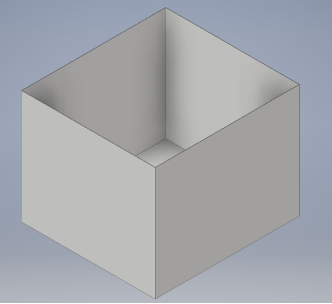
Figure 9: Belt Guard
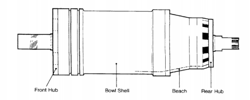
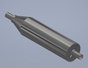
Figure 10: Drum shell with Archimedes screw inside
Drum: The drum (Figure 10) is a cylindrical tube with flanges at both ends. At one end, the liquid discharge drum hub, this is where liquids are discharged from the centrifuge, while on the other side the cake discharge hub is connected, this is where solids are discharged from the centrifuge. The separation medium reaches its maximum speed in the decanter drum. This causes the solids to settle on the wall of the drums inner diameter. This is all a result of the high centrifugal force, which acts on the particles.
One distinctive feature of the drum is its tapered shape. This tapered shape is referred to as the beach. The beach is a conical section at the end of drum. It has this conical shape to exert additional force on the solids, hence squeezing out the last drops of liquid. In this part of the process the centrifugal force push the solids uphill. This design helps to elevate the solids above the waterline in the discharge chamber.
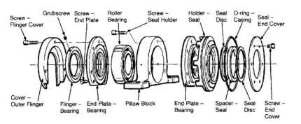
Figure 11: Bearing Setup [2]
Front hub bearings: This horizontal setup (Figure 11) is supported by the use of bearings which are cased in a pillow block. Bearings are used to reduce friction and the effects brought on the component through wear and tear. This bearing used in this assembly is a roller bearing. The roller bearing is a bearing in which the main load is transferred through elements in rolling contact.
Pillow Block: The fundamental application of the pillow block is to mount the bearing safely, which enables the bearings outer ring to be stationary, while the bearing inner ring to rotate. The bearing is supported in a housing and sealed with a non-contacting flinger. This non-contacting flinger is a seal, as the name implies it does not come into contact with the shaft. Its main application is to keep lubricants and grease from escaping, while at the same time it helps keep water, dust and other contaminants that could be harmful, out of the bearing assembly. It does this with the help of the centrifugal force.
Rear hub Bearings: The rear hub bearing assembly is similar to that of the front hub. Its main job is to support one side of the conveyer. This bearing also resists the axial thrust of the scroll.
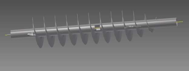
Figure 12: Generated 3D Representation of Conveyor.
Conveyer: The conveyer (Figure 12) is a central hub with a continuous helix welded to it. The conveyer is in the shape of an Archimedes screw fitting inside the drum, between the 2 end hubs. This conveyer will have a small clearance in relation to the drum. It main job is to carry solids which have settled against the walls of the drum, then pushing these solids towards the beach where they can be discharged. Its main functions are to convey the solids after they form a cake, accept the feed and accelerates it up to the drum speed. The material used is EN 1.4571 which is a form of high speed steel (HSS). The conveyer is the transport tool in a decanter centrifuge. The conveyer rotates with a different speed in relation to the drum, subsequently transporting the settled solids towards the conical shape of the drum. Also, the speed at which the conveyer rotates in relation to the drum defines how long a solid spends in the drum. The pitch of the conveyer is related to the transport performance of the centrifuge [2].
This conveyor is comprised of two main sub-components; the scroll, and the shaft. The scroll is welded to the shaft, which rotates. While the two obviously need to be machined separately and welded together for economic reasons, they will be considered as a single part; the conveyor.
Calculations Nomenclature
|
Variable (Motor) |
Description |
|
P |
Power |
|
T |
Torque |
|
̉ۡ |
Angular velocity |
|
Variable (Flow) |
Description |
|
V |
Volume |
|
A |
Cross-Sectional Area of segment |
|
L |
Length of segment |
|
ÃÂÂcake |
Density of cake |
|
Variable (Belt) |
Description |
|
D |
Driver/Motor pulley diameter |
|
d |
Driven/Shaft diameter |
|
n1 |
RPM of shaft |
|
nÂÂ2 |
RPM of motor pulley |
|
|
Angle of contact for shaft |
|
|
Angle of contact for motor pulley |
|
C |
Distance between centres |
|
t |
Thickness of belt |
|
b |
Wirth of belt |
|
l |
Length of belt |
|
η |
Specific weight of belt |
|
ÃÂ |
Density of belt |
|
V |
Volume of belt |
|
m |
Mass per unit length of belt |
|
r |
Radius of pulley |
|
̉ۡ |
Rotational Velocity |
|
FC |
Centrifugal force on belt |
|
F1 |
Tension in tight side of belt |
|
F2 |
Tension in loose side of belt |
|
Fi |
Initial force required to overcome friction |
|
μ |
Coefficient of friction |
|
FR |
Resultant force of belt on shaft |
|
Variable (Deflection) |
Description |
|
E |
Young’s modulus of material |
|
I |
Moment of Inertia of shaft |
|
y |
Deflection in shaft |
|
Variable (Bearings) |
Description |
|
P1 |
Weight of conveyor |
|
P2 |
Force exerted on shaft by belt |
|
RA |
Reaction at bearing A |
|
RB |
Reaction at bearing B |
|
Variable (Shaft) |
Description |
|
|
Bending Stress |
|
|
Shear Stress |
|
M |
Maximum Bending Moment |
|
c |
Outer radius of shaft |
|
I |
Moment of Inertia of shat |
|
T |
Torque applied |
|
J |
Polar Moment of Inertia |
|
router |
Outer radius of shaft |
|
rinner |
Inner radius of shaft |


Calculations and Sizing
Material Selection
Since the machine will make contact with biological materials, certain characteristics and requirements have to be met in order to ensure that the parts making up the centrifuge will not chemically alter or affect the product in anyway. A list of materials suitable for food processing has been compiled by the FDA, based in the US. The 6th iteration of this code, released in 2013, gives specific requirements with regards to materials used in food-contact surfaces of equipment in chapter 4, subpart 4-101.11. Among these requirements are corrosion resistance and durability. Considering this, the material chosen for all the parts that will come into contact with the product; namely the centrifuge and its casing; the chosen material is EN 1.4571 Stainless Steel, which suitably fits all relevant requirements. [4]
REF FDA?
Calculations to find motor requiredÂÂ
Aim: To find the torque required to turn the shaft at a speed of 3800 RPM, which has been determined to be optimal for this machine (Figure 13) and thus find the power needed and an appropriate motor.
Diagram:
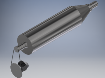
Figure 13: 3D diagram of power transmission system
Due to the complex effects of fluid flow on the resistance to turning, the required torque for operation will be found by reverse engineering a similar system.
HAUS Centrifuge Technologies produce a horizontal decanter centrifuge that has a maximum RPM of 5400, and utilizes a motor with a power output of 11 kW that can process up to around 1 m3/hr of material [5]. This is sufficiently similar to the system being discussed in this report and can thus be used to reverse engineer the torque requirements during steady state.
Using the equation Pdrum = Tdrum̉ۡ, the required torque may be found.
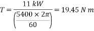
Thus, the required power for the system will be:
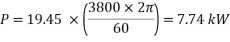
Since the reverse engineered system accounts for power losses due to inefficiencies and other factors, as well as the fact that that system has an overall larger processing capacity, the required power value obtained can be assumed to slightly larger than the true minimum requirement. However, this will account for any power losses during transmission as well as any potential extra power demands.
Conclusions:
The chosen motor is the AEG AM 132M ZA4*. This has a maximum of 1440 RPM and 9.2 kW of power, with an efficiency of 87% when operating at 100% RPM, and a weight of 56kg. This is a modification of the AM 132M ZA4 motor, which only produces 7.5 kW of power [3].
The AM 132M ZA4* is a 4-pole, 3-phase motor, single-speed drive. The motor has a single drive and is an asynchronous type motor with an Aluminium frame. It also has an IP 55 rating, making it somewhat resistant to dirt, debris, and water; a useful property for this use case, where spillages and leakages may occur.
The motor manufacturer also specifies that the chosen motor has a shaft diameter of 38 mm, and a key of 10 x 8 mm should be used for any pulleys, with the keyway being 5 mm deep and 10 mm wide. The key should have a length of 70 mm [3].
Calculations for the sizing of the inlet tube
Aim: To find the required dimension of the inlet tube so that an appropriate amount of material will be input at an appropriate speed.
Diagram:
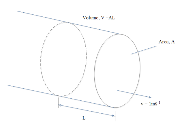
Figure 14: Diagram of flow in inlet pipe
It must first be ensured that the flow rate in the inlet tube (Figure 14) will be sufficient to allow for the design specifications. In this case, the design is specified as having an input rate of 450 kg/hr.
It is assumed that the cake will have a density, ÃÂÂcake of approximately 2000 kg m-3. Thus, the appropriate inner radius may be found.
Converting the input rate to m3/hr:  m3/hr. This results in
  6.225×10⁻⁵ m3 s-1 flow rate.
For a system of this kind, the flow velocity is generally in the range of 0.5 to 2 ms-1. For the sake of calculations, it will be assumed that an appropriate velocity for this specific system will be 1ms-1.
Thus:
Cross Sectional Pipe Area = 
Area = Àr2, therefore   = 4.46 x 10⁻³ m.
Thus, an inner radius of 5mm can be chosen. This will result in a slight decrease in flow velocity, (down to 0.8 ms-1), however this is well within the ideal range. Seeing as this pipe will undergo no torque and very little forces, a standard 2mm thickness can be taken.
Power Transmission
ÂThe centrifuge shaft is required to be turned at a constant speed. The load is determined mainly by flow and amount of cake in the system, which are controlled through a process done by another system. Thus, the load on the system may be assumed to be largely unchanging. The torque required is also relatively low.
As such, a belt and pulley system is an appropriate choice for drive transmission. This is cheaper than a gear train, and is also easier to maintain and replace if required. This also reduces the size of the entire assembly, as the motor may be placed laterally, with the shafts being parallel to each other.
A flat belt is chosen over a V-belt. While the wedging action of a V-belt means that more power can be transmitted, flat belts are more efficient, having a 98% efficiency. Flat belts also generally have a longer work life. Most importantly, flat belts may be used across large centre distances, unlike V-belts. Thus, due to the nature of the setup a flat belt system is more appropriate. [6]
The larger pulley must also be crowned (curved slightly) so the belt may be kept tracking centred on the pulley [7].
Flat-Belt Calculations
Aim: To analyse the forces acting upon the belt, determining friction and tension due to transmitted torque, in order to find forces and stresses on the shafts.
Assumption: A polyamide A-3ᶜ flat belt with thickness 3.3mm is used to calculate the forces present [8].
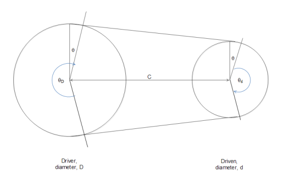
Figure 15: Diagram of belt and pulley system
The outer diameter of the centrifuge shaft has been chosen to be 120 mm. To find the corresponding motor pulley diameter, D (Figure 15) required in order to spin the centrifuge at the required 3800 RPM, assuming the motor will turn at its rated speed of 1440 RPM, the following relationship is used.
dn1 = Dn2
Where nÂ1 ÂÂand n2 are the RPMs of the respective shaft
0.12 3800 = D1440
D = 315.57 mm
This will be approximated to 0.316 m (or 12.5 inches), the closest standard pulley size. For this size, the crown of the pulley should be 1 mm high [9].
Determining the angles indicated [8]:
 = sin-1(
 ) = 0.197ᶜwhere C = 500mm
d = À – 2sin-1() = 2.747ᶜ
D = À + 2sin-1() = 3.536ᶜ
Length of belt, L = 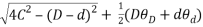 = 1.704m
Thickness and width of belt, t = 3.3mm
             b = 75mm (standard belt width – chosen arbitrarily)
specific weight of belt, η = 0.042lbf/in3 = 1162.56kg/m3
Volume of belt = t x b x l
                        = 75 x 3.3 x 1704
                        = 421.74 x 103 mm3
Mass of belt = ÃÂV = 1162.56 x 4.2174 x 10-4m3 = 0.49kg
Mass per unit length of belt, m =  = 0.2877kgm-1
It can be shown that:
From dS = mr2É dθ                            where dS, is the force due to centrifugal force
              = FC dθ
This implies FC = mr2̉ۡ2
                           =  = 163.34N
The difference in tension between the 2 sides of the belt is given by:
ÃŽâ€F = F1 – F2 =   = 109.3N
For initial tension Fi,
Equating Fi with the force required to overcome friction
Fi = – T2 eμθ from friction equation T1 = T2 eμθ
The negative sign indicates that this is the force that must be overcome.
To find F1 and F2 , Tension in the belt where T1 is the largest tension, to be FI
μ = 0.8
θD = 3.536C
T2 = F2
Since, F2 = Fi + FC – 
F2 = -F2 e0.8 x 3.356 + FC –
F2 = – F2 e0.8 x 3.356 + 163.34 – 
1 – e0.8 x 3.356 F2 = 163.34 –
Therefore, F2 = 
ÃŽâ€F = F1 – F2
109.3 = F1 – 6.06
Therefore, F1 = 115.36N
Finding the radial resultant force on the shaft,
It can be assumed that the force will act approximately radially for the sake of calculations.
By geometry θ = sin-1 = 0.197c = 11.3o
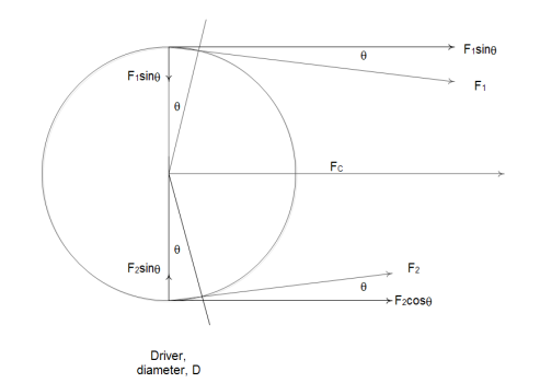
Figure 16: Diagram showing forces acting on driver pulley
Solving horizontally (Figure 16):
(115.36 cos 11.3) + (163.34) + (6.06 cos 11.3) = 282.40N
Solving vertically:
(6.06 sin 11.3) – (115.3 sin 11.3) = -21.42N
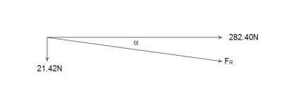
FR =  = 283.45N
α = tan-1 = 4.34o
Calculating FC for the smaller pulley
using the equation FC = mr2̉ۡ2
=> FC =  = 164N
Since FC for the bigger pulley = 163.3N, the resultant force FR will be approximately the same as previously found for bigger pulley.
The chosen belt has an allowable tension per unit width of ~ 31 N/mm, thus the chosen belt may withstand a tension up to 2325 N. Thus, the chosen belt is appropriately sized to withstand any possible loadings for this setup. [8]
Deflection Calculations
Aim: To find the deflection on the centrifuge shaft (Figure 17)
Assumptions:
-It is assumed that the centrifuge shaft will act as a cantilever beam, attached at the bearing, for purposes of deflection.
-The resultant force FR found previously is assumed to be acting from the centre of the belt.
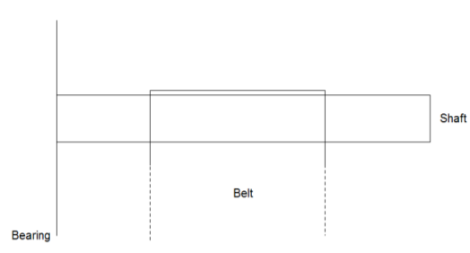
Figure 17: Diagram of belt and shaft
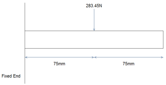
Â
Figure 18: Free Body Diagram of the end of the shaft
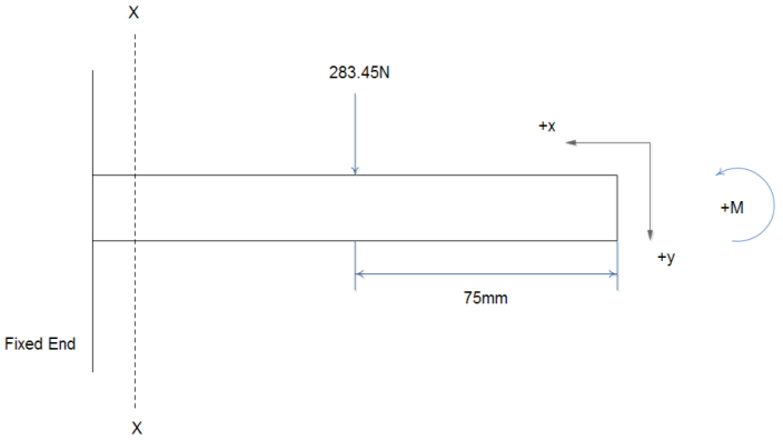
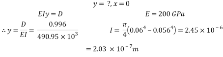
Figure 19: Bending moment diagram of belt & pulley
By Macaulays:
Taking moments about section X-X (Figure 18, Figure 19)
EI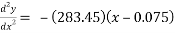
EI
EI
Boundary Conditions


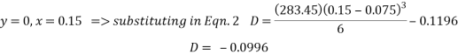
Thus, the deflection will be at most 2.03 x 10⁻⁷ m, acting in the same direction as the resultant force. Since this deflection is so low, it can quite safely be said that the shaft will not bend significantly and will thus not affect the operation of the system at all. This confirms that the chosen dimensions for the centrifuge are correct and it will be fully functional.

Calculations to find the bearings requirements
Aim: To find the loads that the bearings and supports at each end will have to support and thus size and choose the bearings appropriately.
Diagrams:


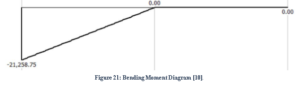
Figure 22: Free Body Diagram of shaft [10]
The decanter shaft (Figure 22) will be treated as a beam for these calculations.
The portion of the shaft being considered is 2260 mm long, being supported symmetrically across a length of 1960 mm by 2 bearings. The reactions will be assumed to act at the centre of contact of the bearings. The shaft also overhangs the bearings by 150 mm on each side.
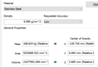
From the Autodesk Inventor iProperties facility, it is known that the centre of gravity, through which the weight will act, is shifted by 121 mm to the left from the centre point of the beam; it is also known that the weight will be 168.2 kg.
There is also an upward force, P2, of magnitude 283 N, acting at one end of the beam, 75mm to the right of the bearing. This is the force due exerted on the shaft by the belt.

 Resolving forces vertically:
RA + RB = (168.2 x 9.81) – 283 = 1367 N
 RA + RB = 1367 N
Where RA and RB are the reactions at A and B respectively.
Taking moments about bearing A:

 (RB x 1.96 m) – (168.2 x 9.81 x 0.859 m) + (283 x 2.035 m) = 0
RB = 429 N
Thus, substituting in the previous equation:
RA = 938 N
Conclusions:
The chosen bearing must be able to withstand at least 1.9 kN (applying safety factor of 2 to the maximum reaction) radially. No significant axial forces will be present.
However, the outer diameter is chosen to be 120 mm thus the bearing must also be of appropriate size. Therefore, the chosen bearing is the UCP324 FHY. This is a pillow block bearing which may be attached using two M33 bolts, is a 120mm bearing, and has a load rating of 207 kN for radial forces and 185 kN for axial loads, making it suitable for this use case. [14]
Calculations to find the decanter shaft thickness
Aim: To find the required thickness for the shaft of the centrifuge, through the analysis of the maximum shear stresses.
Diagrams:
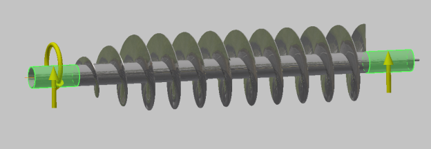
Figure 23: 3D Diagram of Forces and Torques on shaft
Through the maximum shear stress theory, it can be shown that the main stresses acting on a shaft are:
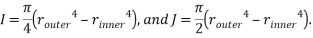
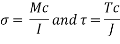 Where M is maximum bending moment, T is the torque applied, c is the outer radius of the shaft, and:
Using stress transformations, and equation for the maximum allowable stress may be obtained [11].

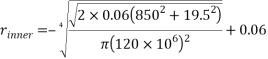
This can be solved for the inner radius:

Thus, if the outer radius is arbitrarily taken to be 0.06 m, the minimum thickness required for the shaft can be found.
However, the bending moment diagram and maximum torque must first be found.
Bending Moments
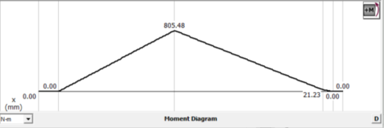
Figure 24: Bending Moment Diagram for shaft [10]
Applying moments at each section of the beam /shaft, the above bending moment diagram (Figure 24) is obtained. As can be seen, the maximum bending moment has a magnitude of 805 N m, and acts at the centre of gravity of the shaft.
Torque
As found previously, the torque required to rotate the shaft at 3800 RPM is 19.5 N m. This is applied through the belt, and will act throughout the shaft.
Thus the above equation may be solved.
The maximum allowable shear stress, Äallow will depend on the yield stress of the material. For 1.4571 Steel, this is 240 MPa[4]. Considering the shaft will not be under very heavy loads and will be encased in the machine, a safety of factor of 2 is considered suitable.
Thus Äallow = 120MPa
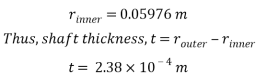
Conclusions:
Since the resulting minimum thickness is so small, an inner diameter of 112 mm is chosen. This is clearly more than sufficient, and will be safer, as well as much easier to manufacture.
Thus, the shaft has an arbitrarily chosen outside diameter of 120 mm and an inner diameter of 112 mm.
References
[1] Australian Olive Oil Association, (2017). Olive Oil Production. [image] Available at: http://www.oliveoilaustralia.com/tree-to-table/olive-oil-production/#toggle-id-2 [Accessed 18 Oct. 2016].
[2] Sutherland, R. &. (2001). Decanter Centrifuge Handbook, 1st Edition.
[3]Asynchronous three-phase motors Technical Catalogue, 1st ed. Lafert Group, 2005. Available:
[4]”AISI 316Ti (1.4571, S31635) Stainless Steel”, Makeitfrom.com, 2016. [Online]. Available: http://www.makeitfrom.com/material-properties/AISI-316Ti-1.4571-S31635-Stainless-Steel. [Accessed: 15- Nov- 2016].
[5] Decanter Centrifuge, 1st ed. Haus Europe, pp. 23-24
[6] The Flat belt drive compared to the V-Belt drive. (2001). 1st ed. [ebook] Habasit. Available at: http://lipsia-componentry.ru/content/files/ploskie/9130.pdf [Accessed 4 Dec. 2016].
[7] Woodgears.ca. (n.d.). How crowned pulleys keep a flat belt tracking. [online] Available at: https://woodgears.ca/bandsaw/crowned_pulleys.html [Accessed 4 Dec. 2016].
[8] J. Shigley, Shigley’s mechanical engineering design, 10th ed. New York: McGraw-Hill, 2011.
[9] Bhandari, V. (2014). Machine Design Databook. 1st ed. [ebook] New Delhi: McGraw Hill Education (India). Available at: https://books.google.com.mt/books?id=Fo7vAwAAQBAJ&printsec=frontcover&dq=Machine+Design+Data+book&hl=en&sa=X&ved=0ahUKEwiq4f6Dr6fRAhWYeVAKHfRXAikQ6AEIGzAA#v=onepage&q=Machine%20Design%20Data%20book&f=false [Accessed 4 Dec. 2016].
[10]MDsolids. 2014.
[11]R. Hibbeler, Mechanics of materials, 7th ed. Upper Saddle River, N.J.: Pearson Prentice Hall, 2008.
[12]N. Schwarz, SELECTING THE RIGHT CENTRIFUGE – THE JARGON DEMYSTIFIED.
[13] Baker Hughes Incorporated, “Solid bowl centrifuge with beach having dedicated liquid drainage”, US5942130 A, 1998.
[14]F. Bearings, “FYH UCP324 120mm Pillow Block Mounted Bearing”, VXB.com Bearings, 2016. [Online]. Available: http://www.vxb.com/FYH-Bearing-UCP324-120mm-Pillow-Block-Mounted-p/kit11403.htm. [Accessed: 18- Nov- 2016].
.
Appendices
|
Drawing No. |
Drawing Description |
|
1 |
Archimedes Screw Orthographic |
|
2 |
Centrifuge Decanter Assembly Orthographic |
|
3 |
AEG AM 132M ZA4 |
|
4 |
Centrifuge Decanter BOM |
|
5 |
Archimedes Screw BOM |
Appendix 1
|
|
|
|
Figure 13: Diagram of the centrifuge [12] |
Figure 14: Diagram of beach angle [12] |

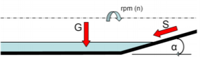
The system also has a taper at one end which is the mechanism through which a major part of separation occurs. The angle of this taper is called the beach or cone angle (Figure 14). This is between 15-450 for many decanter centrifuges [13]. This angle affects the slippage force that acts on the solids in the direction of flow per the relationship:


A smaller beach angle will result in lower slippage force; useful in cases where the solids are soft and do not compact well, such as the olive paste in use in this case. This also provides a lower wear rate on the scroll, thus less maintenance is required. Considering this, a beach angle of 200 is chosen for the system being described.
TO BE DELETED                          …….?
|
Variable (Cake) |
Definition |
|
Qcentrate |
Centrate Rate (m3/h) |
|
QFlocculant |
Flocculant Rate (m3/h) |
|
R |
Recovery Percentage (%) |
|
PD |
Polymer Dosage (kg/t) |
|
N |
Conveyor Differential (RPM) |
|
Ψ |
Thickening Factor (m-1) |
|
Gc |
Centrifuge G-level (N) |
|
Σ |
Sigma (m2) |
|
|
Density Of Olive Oil (kg/m3) |
|
|
Density Of Water (kg/m3) |
|
|
Density Of Cake (kg/m3) |
|
vcake-flow |
Velocity of cake flow (m/s) |
|
Vcake |
Volume Of Cake (m3) |
|
mcake |
Mass (kg) |
|
m˙cake |
Mass flow rate of cake (kg/h) |
|
%wtfeed |
Feed solids (% w/w) |
|
%wtCake |
Cake solids (% w/w) |
|
ÇCentrate Solids |
Centrate solids (ppm) |
|
ΞPolymer |
Polymer Concentration (% w/w) |


|
Variable (Centrifuge Drum) |
Definition |
|
LD |
Length Of Drum (m) |
|
Lc |
Length Of Cone (mm) |
|
router |
Outer Radius of Drum Shaft (mm) |
|
rinner |
Inner Radius of Drum Shaft (mm) |
|
rm |
Mean radius (m) |
|
dbowl |
Diameter Of Bowl (m) |
|
dinner |
Inner Diameter of Drum Shaft (mm) |
|
douter |
Outer Diameter of Drum Shaft (mm) |
|
Pdrum |
Power required for drum (W) |
|
Tdrum |
Torque produced by drum (Nm) |
|
αdrum |
Angular acceleration of drum (rads-2) |
|
ÃÆ’1.4571 |
Yield Strength of 1.4571 Stainless Steel (MPa) |
|
Äallow |
Allowable strain (MPa) |
|
Ämax |
Max strain (MPa) |
|
S.F |
Safety factor (n) |
|
Ix-x(drum) |
Moment of Inertia of drum (kgm2) |
|
tshaft |
Shaft Thickness (m) |
|
ttube |
Tube Thickness (m) |
|
̉ۡDrum |
Bowl Speed (RPM) |
|
Variable (Motor) |
Definition |
|
̉ۡMotor |
Motor Speed (RPM) |
|
Variable (Belt) |
 |