Human Dependent Lighting system
CAREER EPISODE: 01
Human Dependent Lighting system
INTRODUCTION:
1.1) A detailed description of the project “Human Dependent Lightning System” is presented in this career episode. I started this project with a team of three engineers including myself under the guidance of our tutor and head of department, during the initial months of 7th semester, Bachelor of Engineering (Electronics and Communication). This project was implemented as part of my academic curriculum “Project – 1” and it took us three months (July 2012 to September 2012) from inception, testing to implementation of the project. I was appointment as a group leader for this project by our tutor.
BACKGROUND:
1.2) In every department of an industry, there is a wastage of electricity resulting in high electric bills. The wastage of electricity is mainly due to carelessness of users. For instance, lights in various departments would remain switched ON even after working hours, when employees were not present in the office. This leads to unnecessary wastage of electricity. In order to overcome this issue, we developed a human dependent lighting system to use the electricity smartly which can save huge amount of electricity. The human dependent lighting system is a project based on PIR sensors to detect human presence. A light intensity control circuitry is made to turn ON the required number of lights based on surrounding light intensity, thereby reducing the wastage of electricity. This project has a lot of potential and it can be applied to domestic and commercial use.
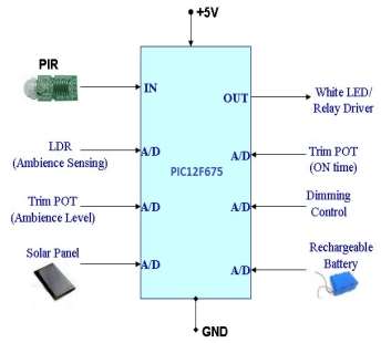
1.3) In Human Dependent Lighting System, we used PIR Sensor which is used to receive the infrared rays that are emitted by human body and Light Dependent Resistor(LDR) to measure the intensity of ambient light. On the output side, we used AC mains supply with loads, such as light connected with relays. These relays are operated based on the output of the controller with specific delays to provide safety to the loads and also to provide intelligent lighting system.
1.4) The system turns ON the required number of lights depending upon the surrounding ambient condition; hence switching OFF the unnecessary lights. The system maintains the required luminous intensity incorporating light received from the surrounding, thus using electricity smartly. Furthermore, we have used PIC12F675 controller equipped with a RISC architecture with inbuilt ADC and MPLAB IDE Version 8.63 software which is used for programming the controller. We have also used a display unit to show intensity levels and number of loads which are switched on.
1.5) Project Objectives
The main objectives of the project are as follows:
- Build a prototype of an energy efficient lighting system with tomorrow’s technology, which will be eco-friendly and for a longer life span.
- Control the lighting system using PIR Sensor and Light Dependent Resistor (LDR) based on the Infrared (IR) light emanation by human or articles in its field of view, and
- Spread the awareness and benefits of using white LED.
1.6) Project Mechanism


1.7) My Roles and Responsibilities as a group leader (Engineer 1) included:
- Researching and selecting the most energy efficient micro controller.
- Programming the microcontroller using MPLAB IDE Version 8.63 software.
- Assisting in designing the circuit.
- Schedule weekly meetings and ensuring attendance of every team member
- Managing and ensuring that each stage of the project was completed within the stipulated timeline, and
- Maintaining the project documentation.
PERSONAL ENGINEERING ACTIVITY
1.8) After the decision to build a prototype for Human Dependent Lighting System was made, the first step I took as a group leader was to select a microcontroller which could act as a brain for the unit and was also programmable. Post which, an exhaustive research referring to different data sheets of microcontrollers was carried out, which enabled me to come up with two appropriate microcontrollers for the project – PIC12F629 and PIC12F675. Both the microcontrollers are PIC12 series microchips having same configuration except one attribute. PIC12F629 lacks Analog to Digital convertor, whereas PIC12F675 has inbuilt 10 bit 4 channels A/D converter which met one of the requirements of the project. Therefore, I selected PIC12F675 microcontroller, an 8-bit RISC architecture based controller used for detecting motion via PIR sensor. It was marked as the IN port for the micro controller. Whenever PIR (Passive Infrared Sensor) Sensor detects a motion due to the human presence or any movement in the room, it acts as an input which makes the lights turn ON.
1.9) One more reason to select PIC12F629 microcontroller, was to connect TRIMPOT to ADC (Analog to Digital converter) to determine the ON time for the system if there is no motion detected. For instance, if Trim POT is set for 10 seconds ON period and if no motion is detected inside the room where system is installed, then system will switch OFF the lights after 10 seconds. We used solar panels to charge the battery during the day time and during the night the system will use the battery to control the lighting systems. We also connected White LED/Relay Driver to OUT port of the PIC controller in order to control the driver or LED based on two inputs conditions: one based on PIR sensors and other from the Trim POT for ON time control. This driver circuit is based on Transistors.
Furthermore, we used LT1086 voltage regulator in order to achieve +5V regulated supply for the system. The LT1086 is accessible in a 3-pin TO-220 bundle and a space-sparing surface mountable 3-pin DD bundle. Therefore, I went with this module, which is very handy and user friendly
1.10) Software Implementation
I used MPLAB IDE Version 8.63 software to program the microcontroller which provides a development environment to perform and program various functions. This software offers memory mapping function to visualize each register. Errors were checked on troubleshooting and debugging the programs by building targets. If it was error free, various simulation ports of the controller were provided to check outputs.
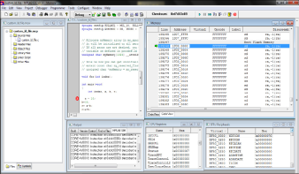
Software Implementation using MPLAB IDE version 8.63
1.11) Pseudo flow:
I used this software since I wanted to achieve the following features:
- Power ON system stabilization time of 30 seconds.
- In 30 seconds, LED will blink with the 250ms ON and 250ms OFF time which is the indication of the stabilization period.
- Stabilize time is required for the PIR sensor which is connected as IN port to stabilize the sensors.
- Default state of White LED is OFF.
- If any motion is detected from PIR sensor it will trigger the IN port of PIC microcontroller.
- If the motion is detected it will send out a signal to the White LED/ Relay Driver, which will turn ON the light.
- If the motion is not detected and if the lights are ON then it will monitor the TRIM POT timing default which is set for 10 seconds and if for 10 seconds no motion is detected, the system will switch OFF the lights.
1.12) Hardware Implementation
Designing of the circuit was an arduous task for us. We completed an exhaustive training program in order to design the circuit proficiently and keeping the IEEE code of conduct guidelines in our mind. The first task was to develop the circuit diagram using EasyEDA software. After following the necessary guidelines to design a circuit, we acquired the skills such as soldering using flux, component placement, placement of ground and power plane, avoid overlapping of analog and digital planes. Furthermore, we took safety measures such as wearing perfect gear for soldering or while connecting the circuit with external power supply. We also read instructions and manuals for understanding implementation of electric components in the safest way. The following picture depicts the basic hardware developed by us for human dependent lighting system.
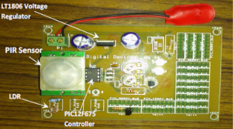
Hardware Implementation
SUMMARY:
1.13) After building the prototype, we completed our project by testing and maintaining the documentation. The project was submitted with a presentation along with the working prototype and reports which was assessed by our tutor and head of the department. The overall project journey was a great experience in terms of learning new skill every day which was a boost to my technical and leadership skills. I faced many ups and downs especially during the training but working with a team was an added advantage for me to divide the load/task in parts and made the implementation of the project successful within the stipulated time. This project has lots of potential and it can be applied to commercial and domestic use.
< >