Intake Manifold of the Internal Combustion Engine
Abstract
Intake manifold of the Internal Combustion engine is a subsystem which supplies fresh air-fuel mixture into the engine cylinders where combustion of fuel takes place. For Efficient Combustion of the charge, the walls of the intake manifold must be smooth/polished to reduce any sidewall resistance. The traditional materials used for intake manifolds were cast iron and Aluminum. In order to reduce manufacturing costs and improve thermal efficiency, new composites are proposed. Inside the cylinder, the energy generated from combustion of fuel is converted into pressure and heat during the power stroke. The pressure and heat increase rapidly within a short span of time. The piston converts this energy into mechanical work. In place of the traditional aluminum alloys, Al-SiC material is proposed which have superior properties. Exhaust manifold is responsible to remove the depleted charge and create space for the incoming charge. Materials used in exhaust systems of engines must have High Temperature Service capability, superior fatigue strength, and good fracture toughness, be easily machinable and economic considering the overall cost of the automobile. Mo-Nb added ferritic stainless steel is a new material that is gaining reputation for its high formability and high heat-resistance.
Introduction
Internal Combustion Engine is a complex machine that does mechanical work when the air-fuel mixture is ignited under high pressure. The Air-Fuel mixture is sent into the Combustion chamber through the intake manifold which is responsible to maintain proper supply of ignition charge into the engine always. The structure of the intake manifold must be such that it has low sidewall friction and maintains lower temperature so that the charge doesn’t pre-ignite. The piston is the component that creates the necessary horsepower inside the engine. It must be light weight and must have good thermal properties. The exhaust manifold deals with the hot gases coming out the combustion chamber. It must be able to maintain flow of exhaust gases without any hindrance. Failure in the exhaust system can cause loss of back pressure which can significantly affect engine performance.
Intake Manifold
1. Introduction
Intake manifold in the car engine is the system which supplies fresh air into the engine cylinders where combustion of fuel happens. The Intake Manifolds in Internal Combustion engines are one of the most engineered components. High precision is needed to efficiently send right amount of cold, high pressure air in equal quantities and at the same pressure. Earlier generations of cars had intake manifolds made from cast iron, which were heavy. In high volume production cars, the use of injection molded composite intake manifolds has been increasing rapidly. [1]
AE 587 Final Research Report – Winter 2017
Material Selection for Intake Manifold, Piston & Exhaust Manifold
Tarun Krishna Prabhakar, Rohit Vedachalam, Pranav Radhakrishna
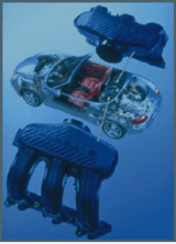
Figure 1: Intake manifold made from Nylon 6,6 [23]
An intake manifold is an integrated unit of any engine, made up of a series of tubes/ducts which distribute fuel-air mixture to each cylinder. For V-shaped engine blocks, intake manifold is integrated between the two cylinder rows whereas inline engines have manifolds to side of cylinder head. Intake manifolds also perform as mounting points for Fuel injectors/carburetors, thermostats, throttle assembly depending on the manufacturer’s engineering designs. Because of the location and functions, intake manifold assemblies experience constant stress from the engine vacuum pressure as direct heat from cylinder combustion gases, and the cylinder head.
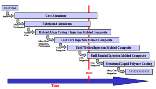
Figure 2: Evolution of Intake Manifold over the years[24]
 Until 1990s, most automotive intake manifold assemblies were made from Cast Iron because of lower cost, or from Aluminum which has lighter weight is required for performance/efficiency. Intake manifolds made from plastic began to gain popularity during 1990s because they offered lower weight and cost combined. They were Factory installed when auto-manufacturers figured out how to manufacture them so that they are durable enough to survive high stresses. [2]
Aluminum is robust metal, but it has few drawbacks. Namely,
1.) It is cheaper to manufacture intake manifolds with advanced composite molding plants than cast out of Aluminum.
2.) Composites have superior heat retention and heat resistance compared to Aluminum and other metals. This means that Phenolic spacers used in previous aluminum intakes are no longer required.
3.) Smoother airflow with lower sidewall resistance compared to Aluminum casting, which requires high level of polishing to achieve same flow of air.
However, there are few disadvantages:
1.) Composites are more flexible, more prone to damage.
2.) Composites or plastics are cheap and deemed unattractive.
Dissimilar materials such as plastic, aluminum, and iron all have different expansion and contraction rates as they change temperature, so gaskets that provide a seal between an intake manifold and a metal cylinder head must be flexible and durable enough to withstand serious pulling and twisting forces. Early ones were not, and leaks resulted along with warpage under intense heat that eventually led to cracks.
Therefore, composites offer several advantages. they saves money, reduces weight, ease of assembly, better insulation, improved airflow, excellent strength to weight ratio, and is recyclable.
1.2. Material Comparison [3]
Properties comparison for PA6 (dry/humid), AL 6082 T6 and 316 stainless respectively:
Yield strength (MPa): 80/45, 260, 290
Elongation at failure (%): 70/200, 8, 50
Ultimate Tensile Strength (MPa): 85/48, 310, 579
Charpy impact toughness (J/square cm): 0.7/8, 10.6, 134
1.3. Existing Material and Process
Material: 319F Aluminum
Cast Component: Aluminum Intake Manifold
Process: Semi Permanent Mold Casting
For a Manifold of an opposed cylinder layout, Intake Manifold alone weighs 4.5 kgs and with the Phenolic spacers it weighs 8.2 kgs. The casting is done by Gravity Tilt Pour process, which can achieve minute thickness upto 3mm. [4]
319F Aluminum is an alloy comprised of 6% Silicon and 3.5% Copper and Iron (<1%). It has excellent properties for sand castings. It has very good Corrosion Resistance and Weldability. Its properties can be even more enhanced by Heat treatment(T5). [5]
Table 1: Properties of 319F Aluminum [26]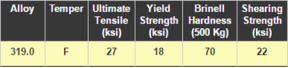
For Aluminum, permanent mold process can be utilized to have sand cores to create complex castings. Die castings cannot use cores made of sand. If cores are used in the permanent molding process, it is sometimes as called ‘semi-permanent molding’ as the mold is permanent but new cores must be made for the next batch.
Permanent mold casting is one of the low-cost method of producing any Aluminum casting. Generally, Permanent mold castings are better than simple sand castings when the factors like ultimate and yield strength are compared. They have better elongation, which is good for ductility. Even appearance of Aluminum in permanent mold castings is better than appearance of castings made from sand casting process, which translates that lesser machining and polishing is required after casting.
The cast is made using a single core. The passageway core is made by coldbox process for making cores, main body core is a blown core type and the external core is made using semi-permanent mold process with three solid cores and one internal passageway core.
Below is a picture of the finished Aluminum Air Intake
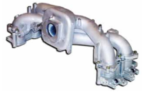
Figure 3: Aluminum Air Intake [25]
1.4. Proposed Material and Manufacturing Process
Material: A-6135 HN PPA(PolyPhthalAmide)
Cast Component: Composite Intake Manifold
Process: Thermoforming
Nowadays, Original Equipment Manufacturers (OEMs) use PA6 or PA66 is used for intake manifolds. In the performance aftermarket, there is possible use of engine performance “enhancers” like nitrous oxide or turbocharging or supercharging, so perhaps a higher-grade composite would be more appropriate.
‘A-6135 HN polyphthalamide (PPA)’ is a 35% glass reinforced resin which is heat stabilized. Main properties of this resin are high strength, high stiffness, and high heat resistance over a broad temperature range. It also exhibits low moisture absorption, good against chemical action and electrical properties.
‘AMODEL A-6135 HSL polyphthalamide’ acts as a solution to both performance and processing requirements. At elevated temperature and humid conditions, the tensile strength of A-6135 resin is 20% stronger than nylon 6, and much stronger than nylon 66. The flexural modulus of this compound is a minimum of 20% greater than stiffness of nylon 6 or 66. [6]
Figure 4: Tensile strength and Flexural strength comparison between composites [26]
For current generation vehicles, plastic intake manifolds are made using the injection molding process. Thermoforming is explored as an alternative to injection molding for making intake manifold shells, which can then be joined by one of the welding techniques used for thermoplastic materials.
There is now an increasing trend in integrating several
components, such as fuel injection, in engine air/fuel modules. The assembly of these components is achieved via either snap fits or threaded fasteners. Increased integration is generally associated with increasing shape complexity. The advantages of shell design in the integration approach are lower number of fasteners required.
Figure 5: Thermoformed Shell type vs Lost Core Design [27]
1.5. Thermoforming
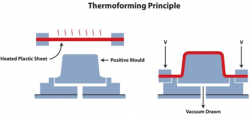
Figure 6: Shows thermoforming principle [28]
It is a manufacturing process in which a plastic sheet is heated to a temperature where it melts and is flowable, to make molding into any predefined shape/pattern and the flash is trimmed to get the final product. Thinner gauges and other materials too are heated in an oven to high temperature which allows the film to stretch or mold and cooled to a final shape. In Thermoforming, Vacuum forming is the simplest method. [8]
Press forming is another type of thermoforming process which is used in work like the sheet metal stamping. Matching metal die set is used here. Preheated plastic sheet is placed on the bottom die and the top die is lowered to close the mold. The hot Plastic sheet gets stretched as the mold closes and then drawn into the shape of die. The sheet is allowed to cool down to take its final shape.
For Complex geometries, the component is divided into 2-3 layers where the molded parts can be assembled and held together by means of fasteners or adhesives.
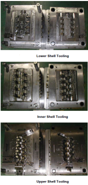
Figure 7: Dies used for Manufacturing Shell type Molding of Intake manifolds [29]
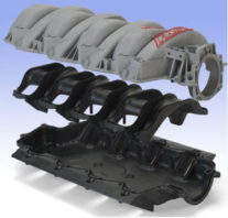
Figure 8: Finished Air intake manifold made of PPA [30]
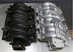
Figure 9: Comparison of PPA and Aluminum intake manifolds [31]
Automotive Pistons
2.1. Introduction
In the cylinder of an engine, the energy of the fuel is converted into pressure and heat during the power stroke. The pressure and heat values increase rapidly within a short interval of time. The piston converts the same into mechanical work [9].
The piston’s structure consists of piston crown, ring belt, skirt and piston boss as shown in Figure1.1. During the power stroke, the forces resulting from the combustion of fuel-air mixture are transferred from the piston crown to piston boss, piston pin, connecting rod and finally to the crankshaft [9].
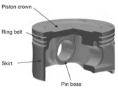
Figure 10: Engine piston [9].
2.2. Forces on piston
The forces acting on the piston are, oscillating inertia forces of the piston and the connecting rod (FK), piston force in the direction of the connecting rod (FST) and lateral force or normal force (FS). During the working cycle, the direction of lateral force changes several times, which oscillates the piston from one end of the cylinder bore to the other, due to the existing piston clearance [9].
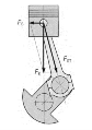
Figure 11: Forces on the piston [9].
2.3. Temperatures in piston
Temperature is an important parameter for the operational safety and service life of a piston. The exhaust gas temperatures, even though is present only for a short period, can exceed more than 2,200°C. In gasoline engines, the exhaust gas temperatures range between 800°C to 1,050°C, and 600°C to 850°C for diesel engines [9].
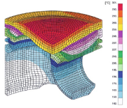
Figure 12:Â Temperature distribution in a gasoline engine piston [9].
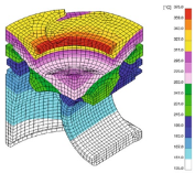
Figure 13:Â Temperature distribution in a diesel engine piston [9].
2.4. Failures of internal combustion engine pistons
Failure of piston is one of the prime reasons for engine breakdown. The failure may occur at different mileage and operating conditions which are usually caused by material defects, engineering, and operational errors. Common causes of piston failures include: 1) insufficient cooling and lubrication of the piston, 2) thermal fatigue, 3) incorrect combustion process, 4) mechanical damage [10].
Figure 14 shows fusion of piston head and ring area in a gasoline engine. It is caused due to a phenomenon called hot bulb ignition occurring on the pistons, primarily on their heads, and in the larger flame extinguishing areas. The hot-bulb ignition occurs in the areas of combustion chamber, which have temperatures higher than the autoignition temperature of the air-fuel mixture. This causes the temperature of the piston head rapidly increase, soften, melt and fuse with the ring [10].
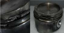
Fig. 14: Fusion of the piston head and the ring area [10].
Figure 15 illustrates a piston skirt seizure. From the figure, it is evident that piston skirt has completely seized. The dark coloring on the surface is due to rough and heavily over- ground abrasion spots. Causes for the failure include: 1) Overheating of the combustion chamber, 2) Poor lubrication, 3) Incorrect combustion process [10].
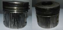
Fig. 15: Piston skirt seizure [10]
Figure 15 illustrates propagation of fatigue crack of the piston pin along the semicircle. This fracture divides the piston head into two parts -as shown in Fig. 5. These are cracks due to excessive loads on the piston pin. The crack grows rapidly with poor lubrication and will ultimately result in the failure of the piston. Causes for the failure include: 1) Incorrect combustion process, mainly by delayed ignition, 2) incorrect starting of the cold engine, 3) hydraulic lock caused by water present in the fuel [10].
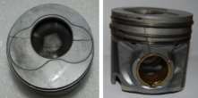
Fig: 16:Â Crack in piston head and skirt [10].
2.5. Materials
Pistons are usually made of Aluminum and Aluminum alloys of eutectic, and partly hypereutectic composition which have high wear resistance. The most commonly used eutectic alloy is M124. Alloys such as M138 and M244 were used in two-stroke engine pistons, while M126 alloy was preferred in gasoline engines. The other recently developed alloys include M142, M145, and M174+, common composition of these alloys include elements of copper and nickel which provides high strength at elevated temperatures and thermal stability. The eutectic alloy M142 and M145 are used in gasoline engines, and the alloy M174+ in diesel engines. Aluminum Metal matrix composites are a new class of materials used in pistons which have superior properties than Aluminum alloys. These composites consist of Aluminum as metal matrix and SiC, Al2O3, TiC, TiB2, Graphite and certain other ceramics as reinforcements [9].
Table 2: Chemical composition of MAHLE Aluminum piston alloys (percent by weight) [9].
|
Elements |
M124 |
M126 |
M138 |
M244 |
|
AlSi12CuMgNi |
AlSi16CuMgNi |
AlSi18CuMgNi |
AlSi25CuMgNi |
|
|
Si |
11.0-13.0 |
14.8-18.0 |
17.0-19.0 |
23.0-26.0 |
|
Cu |
0.8-1.5 |
0.8-1.5 |
0.8-1.5 |
0.8-1.5 |
|
Mg |
0.8-1.3 |
0.8-1.3 |
0.8-1.3 |
0.8-1.3 |
|
Ni |
0.8-1.3 |
0.8-1.3 |
0.8-1.3 |
0.8-1.3 |
|
Fe |
max. 0.7 |
max. 0.7 |
max. 0.7 |
max. 0.7 |
|
Mn |
max. 0.3 |
max. 0.3 |
max. 0.3 |
max. 0.3 |
|
Ti |
max. 0.2 |
max. 0.2 |
max. 0.2 |
max. 0.2 |
|
Zn |
max3 0.3 |
max3 0.3 |
max3 0.3 |
max3 0.3 |
|
Cr |
max. 0.05 |
max. 0.05 |
max. 0.05 |
max. 0.05 |
|
Al |
remainder |
remainder |
remainder |
remainder |
Table 3: Chemical composition of MAHLE Aluminum piston alloys (percent by weight) [9].
|
Elements |
M142 |
M145 |
M174+ |
|
AlSi12Cu3Ni2Mg |
AlSi15Cu3Ni2Mg |
AlSi12Cu4Ni2Mg |
|
|
Si |
11.0-13.0 |
14.0-16.0 |
11.0-13.0 |
|
Cu |
2.5-4.0 |
2.5-4.0 |
3.-5.0 |
|
Mg |
0.5-1.2 |
0.5-1.2 |
0.5-1.2 |
|
Ni |
1.75-3.0 |
1.75-3.0 |
1.0-3.0 |
|
Fe |
max. 07 |
max. 07 |
max. 07 |
|
Mn |
max. 0.3 |
max. 0.3 |
max. 0.3 |
|
Ti |
max. 0.2 |
max. 0.2 |
max. 0.2 |
|
Zn |
max. 0.3 |
max. 0.3 |
max. 0.3 |
|
Zr |
max. 0.2 |
max. 0.2 |
max. 0.2 |
|
V |
max. 0.18 |
max. 0.18 |
max. 0.18 |
|
Cr |
max. 0.05 |
max. 0.05 |
max. 0.05 |
|
Al |
remainder |
remainder |
remainder |
2.6. Current manufacturing process
2.6.1. Permanent Mold Aluminum Pistons
Permanent mold is one of the oldest and common process used for manufacturing pistons. It consists of steel mold with single or multi-piece inner cores to create various intricate features of the piston. This process is a relatively cheap for high volume for a justifiable tooling cost. Parts can be made of various alloys with improved strength at elevated temperatures. High tooling cost and porosity are the main disadvantages of permanent mold process [11].
2.6.2. Forged Aluminum Pistons
Pistons are forged for obtaining high performance, large bore, and increased strength. Heated solid cylindrical aluminum blank is pressed into a die to create piston. The process yields low defective rate, increased ductility, and fracture toughness [11].
2.6.3. Billet machined pistons
Billet machined pistons are machined from the same wrought aluminum materials which are used in piston forging. Billet machined pistons have high surface finish and has no tooling cost. The main disadvantage of this process is high cost [11].
2.7. Improved materials:
Aluminum-Graphite composites were primarily used for automotive antifriction applications. Low cost, good machinability, improved damping capacity are the main advantages of this composite. Aluminum-Graphite composites can be fabricated from various casting processes such as permanent mold casting, squeeze casting, centrifugal casting, and pressure die casting. Pistons made of Aluminum-Graphite composites exhibit properties like, low wear, minimal frictional loss, and elimination of seizure from poor lubrication [12].
Aluminum-Silicon Carbide composites have excellent specific strength, specific modulus and wear resistance. The amount of SiC determines the effect of coefficient of thermal expansion, higher the SiC content, lower the coefficient of thermal expansion. Conventional casting processes such as sand casting, permanent mold casting, investment casting and squeeze casting are used in manufacturing these composites [12].
2.8. Analysis of aluminum and Aluminum-Silicon-Carbide pistons
Firstly, a CAD model of a piston is built in CATIA V6, and is structurally and thermally analyzed using ANSYS 14.0 software [13].

Figure 17: Modeling of Piston and complete assembly [13].
2.8.1. Aluminum composition.
Table 4: Show the chemical composition of aluminum [13].
|
Elements |
Composition |
|
Si |
0.10 |
|
Fe |
0.20 |
|
Zn |
0.03 |
|
Ga |
0.04 |
|
V |
0.03 |
|
Others |
0.10 |
|
Aluminum |
99.5 |
2.8.2. Aluminum Material properties.
Table 5: Shows the material properties of Aluminum [13] [14].
|
Young’s Modulus |
70000 MPa |
|
Poisson’s ratio |
0.35 |
|
Density |
2.7e-006 kg mm-3 |
|
Thermal conductivity |
0.237 W mm-1 C-1 |
|
Bulk Modulus |
77778 MPa |
|
Shear Modulus |
25926 MPa |
|
Coefficient of thermal expansion |
2.48e-005C-1 |
2.8.3. Aluminum-Silicon-Carbide composition.
Table 6: Show the chemical composition of the aluminum alloy (6063) [13].
|
Elements |
Composition |
Elements |
Composition |
|
Si |
0.4430 |
Zn |
0.0001 |
|
Fe |
0.1638 |
Cr |
0.0024 |
|
Cu |
0.0041 |
Ti |
0.0078 |
|
Mg |
0.5832 |
Ca |
0.0003 |
|
Mn |
0.0132 |
Al |
98.751 |
To obtain the composite silicon carbide powder (15% by weight) is added to the aluminum alloy (6063). For example, 150g of silicon carbide is added to every 1kg of aluminum alloy (6063) [13].
2.8.4. Aluminum-Silicon-Carbide composite material properties:
Table 7: Shows the material properties of Aluminum-Silicon-Carbide composite [13] [15].
|
Young’s Modulus |
230Gpa |
|
Poisson’s ratio |
0.24 |
|
Density |
2.937e-006 kg mm^-3 |
|
Thermal conductivity |
0.197 W mm^-1 C^-1 |
|
Bulk Modulus |
1.4744e+005 MPa |
|
Shear Modulus |
92742 MPa |
|
Coefficient of thermal expansion |
0.7e-005C-1 |
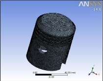
Figure 18: Mesh Model of Piston [13].
2.8.5. Thermal Analysis
Thermal analysis is a technique which analyses the variation of physical properties of a substance as a function of temperature [13].
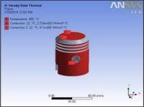
Figure 19: Thermal boundary conditions applied to piston [13].
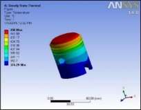
Figure 20: Temperature Distribution in Aluminum piston [13].

Figure 21: Temperature Distribution in Aluminum-Silicon-Carbide piston [13].

Figure 22: Total Heat Flux in Aluminum piston [13].
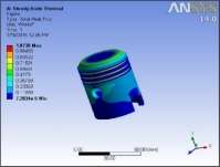
Figure 23: Total Heat Flux in Aluminum-Silicon-Carbide piston [13].
2.8.6. Static Structural Analysis
A static structural analysis helps in determining displacements, stresses, strains, and forces in structures or components. The loads do not take inertia and damping effects in consideration. Assumption: Steady state loading conditions i.e., variation of loads and response of structure are varied slowly with respect to time [13].
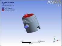
Figure 24: Fixed Support Model of piston [13].
Fig 25: Total Deformation on Aluminum piston [13].
Figure 26: Total Deformation on Aluminum-Silicon-Carbide piston [13].
Figure 27: Equivalent Stress Distribution in Aluminum Piston [13].
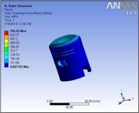
Figure 28: Equivalent Stress Distribution In Aluminum-Silicon-Carbide Piston [13].
2.9. COMPARISON:
2.9.1. Results of static structural analysis
Table 8: Shows the Results of static structural analysis of two pistons [13].
|
Material |
Total Deformation |
Equivalent Stress |
Equivalent strain |
|
Al |
0.19052 mm |
683.22 MPa |
0.00976 mm/mm |
|
AlSiC |
0.060777 mm |
703.54 MPa |
0.0030589 mm/mm |
From the above table, Aluminum-Silicon-Carbide composite has lesser deformation, lesser equivalent strain [13]. However, the equivalent stress of the composite piston is higher than Aluminum piston and this can be reduced by redesigning the stress concentration areas of the piston
2.9.2. Results of thermal analysis
Table 9: Shows the Results of thermal analysis of two pistons [13].
|
Material |
Temperature |
Total Heat Flux |
|
Al |
450 °C |
1.1053 W/mm2 |
|
AlSiC |
450 °C |
1.0738 W/mm2 |
From the above table, Aluminum composite piston has low heat flux and better temperature distribution when compared to a Aluminum piston. Also, Aluminum composites have cooler skirt, and this helps in avoiding skirt seizure [13]. Further, heat treated Aluminum- composites pistons which are manufactured from centrifugal casting will have better thermal properties compared to Aluminum pistons [16].
Exhaust manifold
3. Introduction
The exhaust manifold comes under the “hot-end” of the exhaust systems as the hottest gases, ie. Products of combustion are collected in the manifold after which they pass through the rest of the exhaust system and are finally released into the atmosphere. The hot-end temperature can be as high as 1050 degrees Centigrade.
Cast iron has been in use to produce exhaust manifolds traditionally. The main characteristics required for the exhaust manifold material include thermal fatigue strength required to withstand the high temperature exhaust gases, oxidation resistance and good fabrication. Recent trends towards light weight concepts, cost reduction and better performance, designers are progressing towards sheet metals and ferritic stainless steel as well.
Several factors play into the selection of materials for the exhaust manifold. The most significant of these are:
- high service temperature
- high fatigue strength
- high fracture toughness
- machinability
- economy
Exhaust system materials should also be able to resist corrosion as the components are constantly exposed to road salts, condensates from the engine exhaust gases and other harsh operating conditions. Failure in the exhaust system can cause back pressure, noise etc. which can significantly affect engine performance parameters [17].
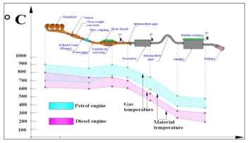
Figure 29: The thermal histogram of the exhaust system for diesel and gasoline vehicles
3.2 Materials currently used
The exhaust manifold is the component that collects and scavenges multiple exhaust fumes from the cylinders through the exhaust valves. It routes exhaust fumes and directs them towards the catalytic converter. The temperature at this area is high. It therefore becomes a necessity that materials with high coefficient of thermal expansion, service temperature, strength, corrosion resistance are used for these applications.
There are two types of manifolds that have been traditionally used. These are cast iron manifolds, and sheet metal/stainless steel manifolds [18].
The materials used for cast iron manifold are variants of grey cast iron such as [18]:
- FCD500-SM1
- FCD550-SM1
Advantages of using Grey cast iron:
- Excellent machinability, thermal conductivity, & damping properties
- Good corrosion resistance
- Reasonable strengths possible (limited by graphite)
Table 10: Physical properties of FCD500-SM1 [19]
|
Quantity |
Value |
|
Thermal Expansion |
10 e-6/K |
|
Thermal Conductivity |
25 W/m-K |
|
Specific heat |
460 J/kg-K |
|
Melting temperature |
1450-1510 deg5 C |
|
Density |
7700 kg5/m^3 |
Table 11: Composition of FCD500-SM1 [19]
|
Element |
Composition |
|
C |
2.5% |
|
S |
0.02% |
|
Mg |
0.09% |
|
Fe |
Rest |
Materials like FCD500-SM1, FCD 550-SM1 are used in manufacturing exhaust manifold due to their high melting point and service temperature. They also have very good strength required to prevent the exhaust manifold from cracking. But the weldability of these materials is relatively lower.
The materials used for sheet metal/stainless steel manifolds are [17]:
- SUS 429LM
- SUS 441L
- SUS 444
Figure 30: The thermal histogram of the exhaust system for diesel and gasoline vehicles
These materials have good high temperature properties such as thermal expansion co-efficient, thermal resistance and service temperature. They also provide required strength, and corrosion resistance, similar to that cast iron materials mentioned above, as well as better weldability due to reduced carbon content [17].
Table 12: Composition of SUS 441 [19]
|
Element |
Composition |
|
C |
>0.03% |
|
Si |
1% |
|
Mn |
1% |
|
P |
0.04% |
|
S |
0.03% |
|
Cr |
17.5-19.5% |
|
Ni |
1% |
|
Ti |
0.1-0.5% |
|
Fe |
Rest |
3.3 Process used
Cast iron manifolds are manufactured by the sand casting process [20] as it is a highly scalable and economical process especially for mass manufacturing. In this process, a pattern or finished part along with metal delivery system such as gates (to direct the flow of molten metal) and risers (to allow tolerances for shrinkages) is manufactured out of various materials like hardwood, urethane, metal or foam. Sand mixed with bonding material (to retain its shape) is packed around the pattern and compacted. The sand, once the pattern is removed, takes the negative shape of the pattern leaving a cavity in the mold. Molten metal is poured into the cavity and allowed to solidify. The sand is removed by mechanical means. Other cast attachments, including the metal delivery system, are trimmed and machined leaving the desired part.
Internal passageways and intricate structures can be included in the sand castings by adding cores during the molding process. Sand castings would typically be at least partially machined before use. Stress relieving heat treatments are performed in order to increase the dimensional stability of the material.
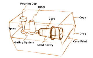
Figure 31: Sand Casting Process [20]
Vacuum casting is a process that is used in the production of ferritic stainless steel manifolds [18]. But this process increases cost by a certain degree.
Vacuum casting [21] is a variation of the sand casting process. A special pattern is used for the vacuum mould casting process. It is either a match-plate or a cope and drag pattern with tiny holes to enable a vacuum suction. A thin plastic sheet is placed over the casting pattern and the vacuum pressure is turned on, causing the sheet to adhere to the surface of the pattern.
 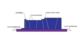
Figure 32: Vacuum casting [21]
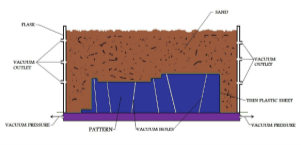
Figure 33: Vacuum casting [21]
3.5 New Material
Ferritic stainless steels have become more and more relevant as the material used in automotive exhaust manifolds. Addition of Mo to 15% Cr ferritic stainless steel shows a good degree of improvement in oxidation/corrosion resistance and high temperature strength. Addition of Si helps in improving oxidation resistance, but it was found to have almost no effect on improving strength at elevated temperatures. Based on these findings, a new Mo-Nb-Ferritic stainless steel was developed [22] which was found to be a more suitable material for usage in automotive exhaust manifolds. The new steel, JFE-MH1 possesses the combined advantages of steels with high formability as well as those with high heat-resistance. [22].
Table 13: Composition of JFE-MH1 [22]
|
Element |
Composition |
|
C |
0.015% |
|
Si |
1% |
|
Mn |
1% |
|
P |
0.04% |
|
S |
0.03% |
|
Cr |
14-16% |
|
Mo |
1.5-1.8% |
|
Nb |
0.4-0.6% |
|
Variant |
Yield Strength (MPa) |
Tensile Strength (MPa) |
% Elongation |
|
JFE-MH1 |
322 |
488 |
34 |
Table 14: Mechanical Properties [22]
Advantages of the new material JFE-MH1 [22]:
- Better formability and weldability
- Better high temperature properties
- Improved oxidation resistance
- Weight reduction
- Improved 0.2% proof stress at elevated tempeartures
- Better tensile strength
Comparison of JFE-MH1 with JFE 429EX and JFE434LN2 (Similar to SUS 444) [22]
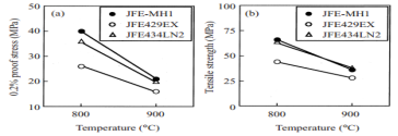
Figure 34: Elevated temperature strength (a) 0.2% proof strength (b) Tensile strength [22]
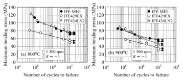
Figure 35: S-N curves obtained by bending fatigue tests at curves obtained by bending fatigue tests at (a) 800°C and (b) 900°C [22]
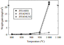
Figure 36: Oxidation test results at 800°C to 1000°C for 400h in air [22]
It was found that, although Si aids in the improvement of oxidation resistance, it adds little or no contribution to 0.2% PS at 900°C. Therefore, Mo use was increased actively in the composition of the developed steel, as it improved both oxidation resistance and 0.2% PS at high temperature. The Si content was reduced leading to the development of a highly heat-resistant and highly formable ferritic stainless steel, JFE-MH1 with the following composition. From the above comparisons, it is clear that JFE-MH1 exhibits better properties overall, when compared to the other materials that are currently used in manufacturing exhaust manifolds [22].
Conclusion
As the intake manifold needs to have materials with smooth surface finish which are easy and quick to produce as well as economical, the material of choice is ‘AMODEL A-6135 HSL polyphthalamide’ as its properties as well as processing requirements are better than that of aluminium or even PA-6 or PA-66 intake manifolds. Al-Si-C in manufacturing pistons provides lower thermal expansion coefficient, high specific strength and high specific modulus of elasticity as well as high wear resistance as compared to traditionally used Aluminum pistons, however the cost of manufacturing slightly higher. Even so, the better mechanical properties compensate for the additional costs. The custom-stainless-steel JFE-MH1 is a material recommended for use in the manufacture of exhaust manifolds as it is capable of providing the necessary thermo-mechanical properties for the harsh use-conditions of the exhaust manifold, as well as improving formability characteristics which makes manufacturing easier. References
- Daniel Agnew, D. and Jay Rohrback G., “Engineering a Composite Intake Manifold for the Performance Aftermarket,” SAE Technical Paper 2004-01-3512.
- https://www.carid.com/articles/why-does-my-car-have-a-plastic-intake-manifold.html#Today_s_Intake_Manifolds__Have_Improved_Plastic_Composites_And_Designs, Retrieved on 03/15/2017.
- https://www.quora.com/How-good-is-polyamide-toughness-compared-to-aluminiums-and-steels, Retrieved on 03/19/2017.
- http://www.afsinc.org/files/MCDP/stories/designsuccess/ciamarapr05.pdf, Engineering Casting Solutions, March/April 2005. Retrieved on 03/17/2017.
- http://www.lbfoundry.com/319-aluminum-sand-casting.html, Retrieved on 03/16/2017
- http://www.canplastics.com/features/first-aftermarket-ppa-air-intake-manifold/, Retrieved on 03/14/2017.
- Eric Carlson and KenNelson, “Nylon Under the Hood:A History of Innovation,” http://www2.dupont.com/Automotive/en_US/assets/downloads/nylon_under_hood.pdf
- Mallick, P.K. & Daly, P. “Investigation of Thermoforming as a Method of Manufacturing Plastic Air Intake Manifolds,” SAE Technical Paper Series, 2000-01-0045
- “Pistons and Engine Testing, Mahle GmbH, First Edition,” (Vieweg Teubner, 2012), ISBN 978-3-8348-1590-3.
- Ambrozik, T. and Lagowski, P., “Selected failures of internal combustion engine pistons,” Institute of Logistics and Warehousing, Volume 3, 48–55, CD 1, 2015. http://dorobek.tu.kielce.pl/publikacje/spisytresci/21110.pdf, retrieved on February 6, 2017.
- http://leadfootengineering.com/piston-manufacturing-technology-options, retrieved on February 6, 2017.
- Mahadevan, R. and Gopal, R., “Selectively reinforced squeeze cast pistons,” 68th World Foundry Congress, OP-72, 379-384, 7th – 10th February, 2008.
- Abino, J. Jenson, T, M. Vasdev, M. and Nitin, D., “Design and Analysis of Piston by SiC Composite Material,” International Journal for Innovative Research in Science & Technology, Volume 1, Issue 12, 578-590, May, 2015.
- Peter Hidnert and H. S. Krider, “Thermal Expansion of Aluminum and Some Aluminum Alloys,” Journal of Research of the National Bureau of Standards, Vol. 48, No.3, 209-220, March 1952.
- http://www.alphamaterials.com/AlSiC.htm, retrieved on march 18, 2017.
- Huang, X., Liu, C., Lv, X., Liu, G., Li, F., “Aluminum alloy pistons reinforced with SiC fabricated by centrifugal casting,” Journal of Materials Processing Technology, Volume 211, Issue 9, 1540-1546, 2011.
- Rajadurai, S., Afnas, M., Ananth, S., Surendhar, S., ” Materials for Automotive Exhaust Systems”, International Journal of Recent Development in Engineering and Technology ISSN 2347-6435(Online) Volume 2, Issue 3, March 2014.
- UKessays.com: Materials Selection for Automotive Exhaust System Engineering (3/8/2017; 6PM)
- Steelgr.com: FCD500 (3/8/2017; 7PM)
- Metaltek.com: Sand Casting (3/10/2017: 10:30 AM)
- Thelibraryofmanufacturing.com: Vacuum Casting (3/10/2017: 10:30 AM)
- Miyazaki, A., Hirasawa, J., Furukimi, O., “Ferritic Stainless Steel for Automotive Exhaust Systems -High Heat-Resistant Ferritic Stainless Steel with High Formability for Automotive Exhaust Manifolds: JFE-MH1”; JFE Technical Report No. 4; Nov 2004
- http://www2.dupont.com/Automotive/en_US/assets/downloads/nylon_under_hood.pdf, Retrieved on 03/17/17
- Daniel Agnew, D. and Jay Rohrback G., “Engineering a Composite Intake Manifold for the Performance Aftermarket,” SAE Technical Paper 2004-01-3512.
- http://www.lbfoundry.com/319-aluminum-sand-casting.html, Retrieved on 03/16/2017
- Daniel Agnew, D. and Jay Rohrback G., “Engineering a Composite Intake Manifold for the Performance Aftermarket,” SAE Technical Paper 2004-01-3512.
- Mallick, P.K. & Daly, P. “Investigation of Thermoforming as a Method of Manufacturing Plastic Air Intake Manifolds,” SAE Technical Paper Series, 2000-01-0045
- http://www.euroextrusions.com/the-principle-of-thermoforming/
- Daniel Agnew, D. and Jay Rohrback G., “Engineering a Composite Intake Manifold for the Performance Aftermarket,” SAE Technical Paper 2004-01-3512.
- Daniel Agnew, D. and Jay Rohrback G., “Engineering a Composite Intake Manifold for the Performance Aftermarket,” SAE Technical Paper 2004-01-3512.
- http://www.lsxmag.com/tech-stories/engine/bbk-ls-