Investigation of Subgrade Reaction Coefficient in Sandy Soil
Numerical investigation of subgrade reaction coefficient in sandy soils
Adel Asakereh1, Hassan Jamali2*, Masoud mossafa1
1 Civil Department, University of Hormozgan, Bandar Abbas, Iran
2Young Researchers and Elite Club, Sabzevar Branch, Islamic Azad University, Sabzevar,
Abstract
The soil-foundation interaction is one of the most important issues in geotechnical engineering relating to soil behavior against side loading. Winkler’s model is the first and simplest method for considering the soil-foundation interaction. Because to determine the coefficient of the subgrade reaction of the soil before designing structure is vitally important, so, experimental, analytical and numerical methods have been proposed. This research chose a ground characteristic that is in Bandar Abbas (Iran). Purpose is to compare the proposed experimental formulae for determining the coefficient of the subgrade reaction with its corresponding values resulting from the behavioral models. Finite element analysis was performed by Plaxis software and important parameters were proposed by the engineers. Results show increasing footing diameter leads to a decrease in the coefficient of the subgrade reaction due to increasing load area which results in increasing settlement. It is found that increasing each of the strength parameters of the soil can be expected to have an effect on increasing the subgrade reaction, although this increase depends on footing diameter. Also in sand soils, the soil cohesion effects on the increase of the subgrade reaction coefficient more than the internal friction angle.
Keywords: Elasticity coefficient, Mat foundation, Subgrade reaction coefficient, Bandar Abbas City, Finite element analysis
- Introduction
The application of mat foundations has a long history. This type of foundation has shown a very good performance in transferring construction forces to the ground. Currently in most cases, engineers use a constant value for the subgrade reaction coefficient to analyze the mat flexible foundations. This constant is obtained from geotechnical experiments such as plate loading. Many researchers have studied soil subsidence and the subgrade reaction coefficient using plate loading test [1-9].
|
Nomenclatures |
|
|
B |
Diameter of footing (m) |
|
|
Minimum marginal dimension of footing(m) |
|
c |
Cohesion (kPa) |
|
d |
Plate thickness (m) |
|
Df |
Embedment depth of foundation(m) |
|
|
Soil elasticity modulus (kPa) |
|
EI |
Flexural rigidity of footing (kN.m2) |
|
EA |
Axial rigidity of footing (kN.m2) |
|
|
Height of ith layer (m) |
|
If , Is, Id |
Dimensionless coefficients |
|
ks |
Subgrade Reaction Coefficient (kN/m3) |
|
m |
Constant coefficients |
|
P |
Vertical pressure (kPa) |
|
Greek Symbols |
|
|
v |
Poisson ratio |
|
|
Vertical Displacement (m) |
|
|
Angle of friction (Degree) |
|
|
Unit weight (kN/m3) |
|
|
Dry unit weight (kN/m3) |


The application of a uniform reaction coefficient over all of the foundation means neglecting the conditions of a continuum for the soil and the effects of cut in the soil layers. One of the fundamental issues in designing and calculating the foundations is the problem of soil-foundation interaction. It is very important to study soil behavior against the external loads. Soil behavior depends on many factors such as moisture content, density, particle-forming mineral types, grain size, grain shape, grading curve, current state of the stress, stress history, pore pressure, saturation point, permeability rate, time, and temperature. In order to study the soil-foundation interaction, many researchers have tried to investigate soil behavior against the imposed loadings to find a model for it. The material model is a mathematical relation for describing the stress-strain behaviour of a small element of the environment.
As previously mentioned, soil behavior depends on many factors it is extremely difficult to provide a model including the effects of all factors. Thus in solving the problems of soil-foundation interaction, some properties of the soil are usually excluded to provide a simpler model with fewer parameters. Since the soil at a macroscopic scale is considered as a continuum, the simplest possible state we consider the soil as a linear, homogenous and consistent elastic semi-space. In such a case, the soil will have two parameters Poisson coefficient and the elastic modulus. The first and simplest model for investigating the soil and foundation interaction is a model offered by Winkler in 1867 [10]. In this model, the deformation of any point of the soil ground is related to the point stress value and the effect of the stresses and the changes in other points are neglected. In this model, soil is replaced with a set of independent springs with a specific stiffness coefficient. Thus, only one single parameter is considered for the soil, that is, the subgrade reaction coefficient represented by ks. One of the most prominent properties of this model is its discontinuous behavior [9]. The subgrade modulus is not a fundamental soil property and its magnitude depends on many factors including the shape of the foundation, the stiffness of the foundation slab, the shape of the loading on the foundation, the depth of the loaded area below the ground surface, and the time. As such, it is not constant for a given type of soil, making the estimation of a single general value for design a challenging task [11]. Consequently, researchers have suggested several ways to determine this parameter and several formulae have been offered for determining ks.
Many researchers have worked on the calculation of subgrade reaction coefficient. Ismail [12] studied the applications of the artificial neural networks (ANN) and the simple-multiple regression analysis to predict the deformation modulus and the coefficient of the subgrade reaction of the compacted soils from the compaction parameters (such as maximum dry density (MDD) optimum moisture content (OMC), field dry density (FDD), and field moisture content (FMC)). Ding [13] compared four typical methods for determining the coefficient of the subgrade reaction including the test method, Lis method, MIDAS method, and finite element method. He showed that the test method is the one preferred by the designers, that the tangential coefficient should be in a range of one to two-third of the normal coefficient. The internal force of subway structures can be obtained by the test method and modified by a correction factor that is 1.05. Barmenkova et al. [14] carried out calculations of plates on an elastic basis with variable and constant coefficients of subgrade reaction. In this paper, the calculation of plates bending was carried out by the finite element method. The results were compared for different models of plates on an elastic basis. For a two-layer plate on an elastic basis, which had heterogeneity in the plan, the results of calculation took into account the increase of the height of the upper structure.
Kobayashi et al. [15] calculated the subgrade reaction coefficient for a foundation soil in an open pier using an extended Kalman filter (EKF) based on measurements taken during in situ horizontal loading tests on a pile. The numerical results would provide useful information for the future design of open piers and their foundations. Liao [16] reviewed the limitations of various simple and complex methods available for estimating the coefficient of subgrade reaction k, and developed a new method using the results of the plane strain finite element analyses of a loaded beam or slab resting on the surface of a homogeneous elastic soil layer.
Although many studies have been carried out on determining the subgrade reaction coefficient, the dependence on many parameters leads to further parametric studies. Experimental and theoretical formulas for determining ks are based on available data from limited sites with some assumptions, so it is possible for them not to have sufficient precision in all areas. Therefore, determining the subgrade reaction coefficient in specific areas such as Bandar Abbas city and assessment of the effective parameters on subgrade reaction coefficient is vital. Besides, the Increasing in footing width, increases effective depth. Therefore, determination of ks in footing with more width is more complex especially in layered soil, because ks obtained from plate load test is different from ks under real loading of structure. Thus investigation of the footing width and the strength parameters of the soil on ks is needed. Performing plate load tests with large diameters is expensive and difficult, thus the present study uses finite element software of Plaxis to investigate the effect of the aforementioned parameters.
Parametric studies on subgrade reaction coefficient of sand soil in Bandar Abbas city are few, so this paper uses geotechnical data of a site in Bandar Abbas city (Iran) to determine subgrade reaction coefficient by using of theoretical, experimental relations and numerical methods. Besides, the effects of the strength parameters (c, ) and B on subgrade reaction coefficient are investigated too. This study is carried out by using and verifying numerical methods and ensuring the accuracy of the software. Numerical analysis has been done by finite element method using Plaxis software [17].
- Analytical methods of subgrades reaction coefficient
In order to obtain ks, one can generally apply plate loading, consolidation, triaxial, and CBR tests and experimental and theoretic relations provided by researchers [18]. Among them, plate loading testing and the experimental method are considered the most common methods. In this paper, experimental and theoretic methods are considered. There are several relations including Vesic [19], Biot [20], and Bowles [6] as well as relations resulting from elastic theory from elasticity theory to determine subgrade reaction coefficient.
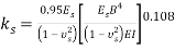
Biot [20] solved the problem of an infinite beam on a linear elastic subgrade and provided Eq. (1) for subgrade reaction coefficient.
|
(1) |
|
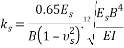
Vesic [19] developed Biot’s work [20] and suggested Eq. (2) for the relation between ks and elastic characteristic of soil:
|
(2) |
|
He also showed the difference between Winkler method and continuum does not exceed 10 percent. Bowles [6] showed the numerical value of   in ordinary condition may be approximated by 1, and in most cases subgrade reaction coefficient is obtained by Eq. (3):
|
(3) |
|

Using elasticity theory is another way to approximate ks. By reformulating the elastic subsidence in rectangular foundation, we obtain the following [21]:
|
(4) |
|
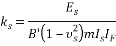
These values are determined based on tables in the elastic subsidence section of basic soil mechanic references. “m” is the coefficient which is equal to 1, 2 and 4 for corner, edge, and center, respectively. ks is calculated in corners assuming m = 1 from Eq. (4) and it is multiplied by 0.5 to obtain k edges or by 0.25 to obtain ks centers. According to the above discussion, it can be seen that there are several formulae to determine soil subgrade reaction coefficient.
- General and geotechnical properties of the soil
The site of the residential- mercantile building is located to the west part of Bandar Abbas city in Iran (Fig. 1) with seven floors over the ground floor (parking lot). The depth of the foundation settlement is equal to the height of the foundation as 1 meter and no groundwater grade was observed until the end of the excavation depth. In order to identify the underground layers, five boreholes were excavated (three 15-meter boreholes and two 20-meter boreholes) using a rotary drilling machine. During soil boring, some samples were extracted for laboratory experiments. After completion of the field operation, the extracted samples were tested for grading, Atterberg limits, moisture content of the natural soil, and direct shear test. The studies on the layers of the site soil show the soil type in the foundation subgrade is mainly silty sand (SM) from the ground level down to the depth of 8 meters, and the soil type is bad-grained sand (SP) from the depth of 8 meters downwards.

Fig. 1. Location of Bandar Abbas city.
Considering the field and laboratory experiments in order to determine the scale of soil subsidence and the bearing capacity of the site soil, the required parameters were selected from the five excavated boreholes as shown in Table 1. The data of the samplings is available down to 20 meters deep. The soil type was given down to the depth of the foundation effect (around 30m). Moreover, the soil weight at the 20 to 30 m depth (layer 11) has considered as being constant.
Table 1. Soil properties of the site
|
No. of Layers |
Dep. (m) |
Soil Type |
SPT (Ncor.) |
ω (%) |
c (kPa) |
φ (˚) |
γ (kN/m3) |
γd(kN/m3) |
|
1 |
0-2 |
SM |
21 |
4.1 |
0 |
29 |
17 |
16.3 |
|
2 |
2-4 |
SM |
17 |
16.6 |
0 |
29.1 |
18.6 |
16.23 |
|
3 |
4-6 |
SM |
24 |
14.9 |
0 |
28.8 |
18.6 |
16.18 |
|
4 |
6-8 |
SM |
33 |
15.2 |
0 |
30.4 |
18.9 |
16.4 |
|
5 |
8-10 |
SP |
38 |
23.7 |
0 |
32.4 |
20.1 |
16.24 |
|
6 |
10-12 |
SP |
39 |
18.1 |
0 |
31.2 |
19.4 |
16.42 |
|
7 |
12-14 |
SP |
47 |
24.2 |
0 |
31.2 |
20.6 |
16.58 |
|
8 |
14-16 |
SP |
50 |
19.8 |
0 |
30 |
20 |
16.69 |
|
9 |
16-18 |
SP |
50 |
19.2 |
0 |
32 |
20 |
16.77 |
|
10 |
18-20 |
SP |
50 |
18.8 |
0 |
32 |
20 |
16.83 |
|
11 |
20-30 |
SP |
50 |
18.8 |
0 |
32 |
20 |
16.83 |
Equations (5) and (6) were used to determine the elasticity modulus of the soil [6]:
|
|
(5) |
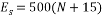
For unsaturated sands, and
|
|
(6) |
For saturated sands.
Thus, the elasticity modulus for each of the soil layers is calculated based on the above formulae and the results are shown in Table 2.
Table 2. Elasticity modulus of the soil layers
|
No. of Layers |
SPT (Ncor.) |
Es (kPa)-dry |
|
1 |
21 |
18000 |
|
2 |
17 |
16000 |
|
3 |
24 |
19500 |
|
4 |
33 |
24000 |
|
5 |
38 |
26500 |
|
6 |
39 |
27000 |
|
7 |
47 |
31000 |
|
8 |
50 |
32500 |
|
9 |
50 |
32500 |
|
10 |
50 |
32500 |
|
11 |
50 |
32500 |
- Numerical analysis procedure
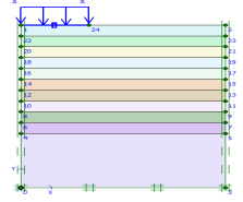
First, the results of Brian Anderson et al. [22] were analyzed with Plaxis to verify the software. Brian Anderson et al. [22] performed in situ testing and numerical investigation for predicting settlement of shallow foundations. Accordingly, a 1.8 m diameter concrete footing was statically load tested. Prior to construction, in situ standard penetration test (SPT), cone penetration testing (CPT), dilatometer (DMT), and pressuremeter (PMT) and laboratory tests were performed to determine engineering properties of the soil. A reinforced circular 1.8 m diameter 0.6 m thick concrete footing was constructed using a corrugated pipe coupler as a form. To overcome a thin hard layer surface crust, the footing was embedded 0.6 m into the ground. The groundwater table was at 1.7 m from the ground surface, as illustrated in Fig. 2. Static load was 222 kPa. Due to the symmetry, half of footing with the width of 0.5 B is modeled asymmetrically. Avoiding boundary effects, a 6.5Ã-5 m model was selected. The model depth was taken as 6.5 m, that is approximately equal to 4B=6.8 m and the width of the model was taken as 5 m, that is approximately equal to 3B [23] . Results proved that the displacement did not reach the boundaries in the analysis. To investigate the mesh dependency, a number of trial analyses were conducted through the verification study. The model included 1971 nodes and 235 elements. The boundary lines were defined as the limited deformation in horizontal direction and free deformation in vertical direction, and limited deformations both in horizontal and vertical directions at the lower boundary as showed in Fig. 3. Trial analyses proved that with specified dimension and meshing, errors would be negligible. In order to do the modeling with finite element method, the 15-node triangular element was used according to Fig. 4. Table 3 presents the input parameters used for the FEM analyses. Figure 5 presents applied stress-settlement diagram obtained from Plaxis in this study and reference to a point located under plate. There was a negligible difference between two diagrams, so Plaxis was suitable for analysis.
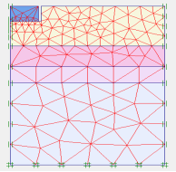
Fig. 2. Geometry and mesh of the verification model.     Â
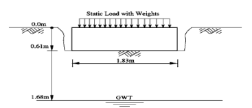
Fig. 3. Soil-footing profile of verification model                                                                           [22].
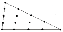
Fig. 4. 15-node triangular element.
Table 3. Soil properties used in verification according to [22].
|
Bottom(m) |
|
|
E(Mpa) |
c(kPa) |
|
1.64 |
18.9 |
31.4 |
14.5 |
0 |
|
2.5 |
17.3 |
30.1 |
12.5 |
0 |
|
3.17 |
15.7 |
28.6 |
10.50 |
0 |
|
6.5 |
14.2 |
27.1 |
8.5 |
0 |
 (kN/m3)
 (deg)
(deg)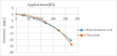
Fig. 5. Applied stress-settlement diagram.
After software verification, the model was developed for determining the subgrade reaction coefficient of Bandar Abbas city and parametric study. In the created model (which included 2011 nodes and 256 elements), the loading was uniform and, a rigid foundation was considered in all phases of analysis. Model depth should be greater than 4B and model width greater than 3B for different diameters. Since it was intended to study the effect of foundation diameter on determining the value of subgrade reaction coefficient, an asymmetric model was used in the software for soil modeling. The relevant parameters of the general properties (wet and dry specific weight) and the relevant parameters of the soil resistance (c,) for all soil layers were derived from Table 1. Considering the results of the experiments and researches and the reliability of the developed numerical model with the results, and considering the soil type of the site (sand soil), Mohr-Coulomb behavioral model for the soil was used in this research. Since in Mohr-Coulomb behavioral model the stress-strain relation is fulfilled directly by the soil elasticity coefficient, thus in entering the data of the soil elasticity coefficient as one of the input parameters, the data of Table 2 were used. The values of the dilation angle in all layers were assumed to be 0. Considering the properties of the building in this project and the scale of the imposed loading (dead and live load), the value of the imposed pressure on the soil was assumed to be 120 kN/m2 where the plate element (with the concrete foundation properties) was used to transfer this load to the modeled soil. Among the most important properties of the element, it could be referred to its flexural hardness (EI) and its axis hardness (EA). These two parameters can be used to obtain the plate thickness that is the representative of the foundation thickness in this case. Considering the constant thickness of the foundation by 1 meter in this research, different values would be obtained for EI and EA in different models according to the Eqs. (7) and (8) [24]. Since the modeling was done with asymmetric method, thus half of the diameter of the real foundation was modeled, and the modeling was done in direction of x-axis, three times more than the foundations diameter (3B), and in the direction of y-axis equal to the number of the layers mentioned in Table 1. Moreover, Table 4 shows the parameters needed for determining the plate input parameters into Plaxis software.
|
d= ½ deq |
(7) |
|
|
(8) |

|
|
|
Fig. 6. Geometry of the model. |
|
Table 4. Plate parameters |
|||
|
EI (kNm2/m) |
EA (kN/m) |
E (kPa) |
Df(m) |
|
Var. |
Var. |
2.5Ã-107 |
1 |
- Results and discussion
Seven models were developed for different values of foundation diameter (8, 10, 12, 14, 16, 18, and 20 m). Then, they were analyzed by finite element method using Plaxis. Because of axis plain strain in Plaxis, foundation is considered as a strip with B/2 of diameter and 1 m, orthogonal to the plane as shown in Fig. 6. Amount of vertical displacement in center and below of the foundation (sections are in center and 1 meter below the above subgrade of soil model) is obtained according to the load determined by the construction analysis (120 kN/m2). The soil subgrade reaction coefficient is calculated by Eq. (9) for any values of foundation diameter [25]:
|
(9) |
|

The soil subgrade reaction coefficient (ks) resulted from numerical analysis for several foundations are shown in Fig. 6. The vertical settlement ( ) obtained for each layer is plotted in terms of constant contact pressure (P) of about 120(kN/m²) plotted and then, the secant modulus of each graph (ks) is determined.
|
  (b) |
     (a) |
|
Fig. 7. (a) Settlement variations (b) ks variations for several values of foundation width resulted from numerical analysis. |
|
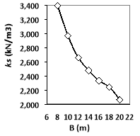
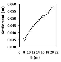
As it can be seen from Fig. 7, an increase in foundation diameter causes an increase in settlement but it decreases subgrade reaction coefficient. This is due to the increase in load area which results in higher settlement [26]. If foundation diameter increases from 8 to 20 meters, then settlement changes from 35 mm to 58 mm, i.e. when foundation diameter is increased by 2.5 times, its settlement increase by 67% and subgrade reaction coefficient changes from 3400 MN/m3 to 2068 MN/m3 which means it decreases by 60%. Generally, there is a linear relation between the decrease in foundation’s diameter and settlement and the decrease in subgrade reaction coefficient.
- Analytical determination of subgrade reaction coefficient
In applying formulas in Section 2, which are summarized in Table 5, approximating elasticity coefficient should be precise, since this value is the only factor for the effect of bedding on ks. Hence, it is used as the corresponding elasticity coefficient which contains all layers locating in the foundation effect depth.
Table 5. Analytic formulas for ks used in this paper.
|
Relationship |
Reference |
Method |
|
|
Biot [20] |
1 |
|
|
Vesic [19] |
2 |
|
|
Bowles [6] |
3 |
|
|
Elasticity Theory[21] |
4 |
Equation (10) is for calculating the corresponding elasticity coefficient [24]:
|
(10) |
|

Therefore, the elasticity coefficient is obtained as 28134kPa after using elasticity modulus of Table 2 and thickness of layers and substituting them in Eq. (8). On the other hand, since the effect of load decreases by depth, elasticity modulus of upper layers will be higher than that of lower ones. Therefore, this effect is included by adding a factor called depth factor (ID), and finally Eq. (11) was used to calculate the corresponding elasticity modulus [27]:
|
(11) |
|

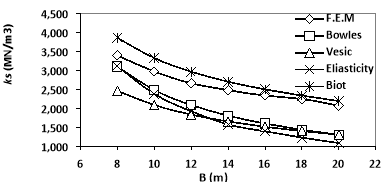
In any layer, depth factor is the ratio of displacement in center of the layer to the total displacement in Plaxis. Another way is to divide imposed stress in center of the layer to the total imposed stress (120 kPa). According to this, the corresponding elasticity modulus, which obtained from (11), is between 22595 kPa and 23736 kPa. The variations of subgrade reaction coefficient resulted from experimental and numerical analysis is shown in Fig. 8. The Figure 8 shows that although in low diameter (around B=8m) ks of finite element method and Vesic and bowels are close together, ks of finite element method and Biot become closer with the increase in B.
|
|
|
Fig. 8. ks variations for several values of foundation diameter resulted from analytical and numerical analysis without groundwater level. |
- Effects of strength parameters of soil on the subgrade reaction coefficient
Since in most projects, soil is treated on the upper layers leading to some changes in its mechanical properties, thus it was tried to express the effect of the cohesion and the internal friction angle on the value of the subgrade reaction coefficient from this numerical analysis. In this regard, the mentioned operation was conducted at three steps [26]. The first step was to conduct the cohesion. So in layers 1 and 2 and in the definition of the properties of soil layers in Plaxis software, the values of cohesion was entered with four different values (i.e. 5, 10, 15 and 20 kPa) and all 7 files were analyzed separately based on these values. The second step was to apply the internal friction angle alone. Therefore, in layers 1 and 2 and in the definition of the properties of soil layers in Plaxis software, the values of friction angle was entered with two different values (i.e. 35 and 40 degree). Finally, in the third step, both parameters of cohesion and angle of the internal friction were applied together in layers 1 and 2 and in the proposed model and the values were numerically analyzed. The results showed that the joint effect of both parameters was plastic and merely with the internal friction angle of 40 degree. The obtained results of the analysis in different states are shown in Figs. 7 and 8.
|
              (a) |
|
              (b) |
|
Fig. 9. The effect of (a) foundation diameter and (b) cohesion on the ks changes. |
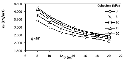
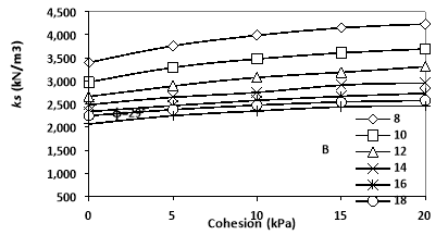
As shown in Fig. 9, the increase in the cohesion value in the soil layer led to the increase in Ks value, and this increase was lower in wider foundations, so that in the foundation with 8 m diameter, the average increase in ks value in all four cases (of 10, 5, 10, 15 and 20 kPa) of the cohesion value is equal to 18.6% and in the foundation with 20m width, it was equal to 14.8%. Moreover, it can be observed that this amount of increase in ks value had an approximately equal slope in different diameters.
|
|
|
Fig. 10. The effect of internal friction angle on ks changes resulted from the numerical analysis. |
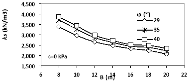
Figure 10 implies that the increase in the internal friction angel will lead to the increase in ks value, and this increase is lower in wider foundations, so that in the foundation with 8 m diameter, the average increase in ks value in both angles of 35 and 40 degrees was equal to 11.68% and in the foundations with 20 m diameter, it was equal to 10.5%. Moreover, it can be observed that this amount of increase in ks value had an approximately equal slope in different diameters.
|
        (a) |
|
|
      (b) |
|
|
Fig. 11. The effect of (a) foundation diameter and (b) cohesion on the ks changes resulted from the numerical analysis. |
|
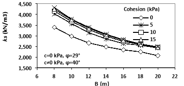
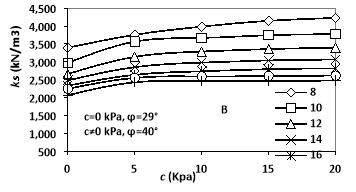
Figure 11 shows both strength parameters of the soil so that ks value increased with the increase in both mentioned parameters, and like the previous steps, this increase was lower in wider foundations; i.e. in the foundation with 8 m diameter, the average amount of the increase in ks value was equal to 23.32% and in the foundation with 20 m diameter, it was equal to 18.95%.
- Conclusion
The results of this analysis and comparison are as follows:
- The increase in the foundation diameter will lead to the decrease in ks value, so that ksvalue is decreased by 10% with the 2-m increase in the diameter of the foundation. This result proves that the coefficient of subgrade reaction is not a soil property and depends on the size of the loaded area and footing.
- Among all suggested formulas for determining the subgrade reaction coefficient, the Biot method is more compatible with the results of the numerical analysis in different diameters of the foundation; and in the subjected soil of this research, we can claim that the Biot method is the dominant formula for determining the subgrade reaction coefficient.
- Elasticity modulus is equal to one of the effective parameters for determining the subgrade reaction coefficient especially in layered soils; its effects are further eminent. That assumes the effect of the increase in the elasticity coefficient of the upper layers into the lower layers.
- Strength parameters have a positive effect on the increase in the subgrade reaction coefficient of the sand soil so that depending on the diameter of the foundation, the subgrade reaction coefficient can be increased up to 23% by changing the mechanical properties of the lower layers of the foundation. It is found that each of the strength parameters of the soil (
 ) can be expected to have an effect on increasing the subgrade reaction coefficient up to 18.6 and 11.86% for cohesion and the internal friction angle, respectively. It can be related to the fact that increasing strength parameters increases stiffness of soil. In sand soils, the cohesion of the soil is more effective on the increase in the subgrade reaction coefficient than the internal friction angle. This result shows that subgrade reaction coefficient depends upon some parameters like soil type, size, shape, depth, and type of foundation.
References
1.Terzaghi, K., Evalution of conefficients of subgrade reaction. Geotechnique, 1955. 5(4): p. 297-326.
2.Bond, D., The influence of foundation size on settlement. Geotechnique, 1961. 11(2): p. 121-143.
3.Teng, W.C.-Y., FOUNDATION DESIGN. 1962.
4.Bjerrum, L. and A. Eggestad. Interpretation of loading test on sand. in Proceedings of European Conference in Soil Mechanics. 1963.
5.Broms, B.B., Lateral resistance of piles in cohesive soils. Journal of the Soil Mechanics and Foundations Division, 1964. 90(2): p. 27-64.
6.Bowles, J., Foundation analysis and design ″ McGraw-Hill Book Company. 1982, NY.
7.Parry, R., Estimating foundation settlements in sand from plate bearing tests. Geotechnique, 1978. 28(1): p. 107-118.
8.Arnold, M., Prediction of footing settlements on sand. Ground Engineering, 1980. 13(2).
9.Suoqing, Z., Z. Xiping, and P. Haili, Study on foundation soil coefficient of subgrade reaction. Chinese Journal of Underground Space and Engineering, 2005. 1(7): p. 1109-1112.
10.Winkler, E., Theory of elasticity and strength. Dominicus Prague, Czechoslovakia, 1867.
11.Larkela, A., M. Mengelt, and T. Stapelfeldt. Determination of distribution of modulus of subgrade reaction. in Proc., 18th Int. Conf. on Soil Mechanics and Geotechnical Engineering, French Society for Soil Mechanics and Geotechnical Engineering (CFMS), Paris, France. 2013.
12.Dinçer, Ä°., Models to predict the deformation modulus and the coefficient of subgrade reaction for earth filling structures. Advances in Engineering Software, 2011. 42(4): p. 160-171.
13.Ding, D.Y. Discussion on Determination Methods for Coefficient of Subgrade Reaction in Response Displacement Method. in Applied Mechanics and Materials. 2014. Trans Tech Publ.
14.Barmenkova, E.V. and A.V. Matveeva, Calculation of Plates of Variable Rigidity on Elastic Foundation with Variable Coefficient of Subgrade Reaction. Procedia Engineering, 2015. 111: p. 97-102.
15.Kobayashi, N., et al., Estimation of horizontal subgrade reaction coefficient by inverse analysis. Computers and Geotechnics, 2008. 35(4): p. 616-626.
16.Liao, S. Estimating the coefficient of subgrade reaction for plane strain conditions. in Proceedings of the Institution of Civil Engineers: Geotechnical Engineering. 1995.
17.Plaxis, B., User’s manual of PLAXIS. 2002, AA Balkema Publishers.
18.Lin, P.-S., L.-W. Yang, and C.H. Juang, Subgrade reaction and load-settlement characteristics of gravelly cobble deposits by plate-load tests. Canadian geotechnical journal, 1998. 35(5): p. 801-810.
19.Vesic, A. Beams on elastic subgrade and the Winkler’s hypothesis. in Proceedings, 5th International Conference on Soil Mechanics and Foundation Engineering. 1961.
20.Biot, M., Bending of an infinite beam on an elastic foundation. Zeitschrift fiir Angewandte Maihematik und Mechanik, 1922. 2(3): p. 165-184.
21.Horvath, J.S., Modulus of subgrade reaction: new perspective. Journal of Geotechnical Engineering, 1983. 109(12): p. 1591-1596.
22.Anderson, J.B., F. Townsend, and L. Rahelison, Load testing and settlement prediction of shallow foundation. Journal of Geotechnical and Geoenvironmental Engineering, 2007. 133(12): p. 1494-1502.
23.Mosallanezhad, M., N. Hataf, and A. Ghahramani, Three dimensional bearing capacity analysis of granular soils, reinforced with innovative grid-anchor system. Iranian Journal of Science and Technology, 2010. 34(B4): p. 419.
24.Sadrekarimi, J. and M. Akbarzad, Comparative study of methods of determination of coefficient of subgrade reaction. Electronic Journal of Geotechnical Engineering, 2009. 14: p. 1-14.
25.Ismael, N.F., Allowable pressure from loading tests on Kuwaiti soils. Canadian Geotechnical Journal, 1985. 22(2): p. 151-157.
26.Ismael, N. and H. Al-Sanad, Plate loading tests on weakly cemented surface desert sands. Geotechnical Engineering, 1993. 24(2).
27.Marto, A., et al., Foundation Size Effect on Modulus of Subgrade Reaction on Sandy Soils. Electronic Journal of Geotechnical Engineering, 2012. 17.