Polarization Maintaining Octagonal Photonic Crystal Fiber
Polarization maintaining octagonal photonic crystal fiber
Designed for residual dispersion compensation
Over S+C+L+U wavelength bands
Ouadah Mohammed Chamse Eddine1*, Chikh-Bled Mohammed El Kebir1
1Telecommunications Laboratory of Tlemcen(LTT), Faculty of Technology,Abou Bekr Belkaid University
Tlemcen13000 ,Algeria
E-mail: ,
Abstract
An octagonal photonic crystal fiber is proposed and designed for dispersion compensation caused by the single mode fiber over S to U wavelength bands telecommunication. Based on finite element method with perfectly matched layers (PML), it is shown that the negative chromatic dispersion of about -928 ps/nm/km and the relative dispersion slope exactly to the single mode fiber (SMF-28) of about 0.0036 nm-1at wavelength  =1.55 µm. In addition, the birefringence is about 1.86
 10-2 at the same wavelength. Due to these properties, our proposed fiber has several applications as broadband dispersion compensation and sensing applications.
Key words: octagonal photonic crystal fiber, chromatic dispersion, Relative dispersion slope, birefringence, finite element method, single mode fiber.
- Introduction
In dense wavelength division multiplexing (DWDM), chromatic dispersion is one major problem, which affect the quality of transmission and bit rate [1]. To eliminate this effect, several methods are used such as dispersion shifted fiber (ITU-T G653) [2], non-zero dispersion shifted fiber (ITU-T G655) [3], fiber gratings [4].
Recently, a new kind of fibers called Photonic crystal fibers [5] or Holey fibers [6] have diverse applications such as dispersion compensation [7], birefringence [8], non-linearity [9] which not achieved with the conventional fibers. To compensate the chromatic dispersion with the photonic crystal fiber, it is necessary that have a high negative chromatic dispersion coefficient [11].
Until now, many designs of photonic crystal fibers with high negative chromatic dispersion have been proposed. For instance, photonic crystal fiber based on octagonal lattice geometry in [12] presents a chromatic dispersion coefficient of about -239.5 ps/nm/km and a high birefringence of about1.67 10-2. Some other fiber is presented in [13] with a chromatic dispersion coefficient of about-868 ps/nm/km. On the other hand, M. Mejbaul Haque et al propose a hybrid photonic crystal fiber with a chromatic dispersion coefficient of about -650 ps/nm/km [14].
In this paper, an octagonal photonic crystal fiber has been proposed for broadband dispersion compensation over S to U bands wavelengths telecommunication. The results reveal that a negative chromatic dispersion of about -928 ps/nm/km and a birefringence of about 1.8610-2 at the operating wavelength 
These characteristics make the O-PCF usable in transmission network (DWDM) and sensing application. One, more advantage over the proposed fiber is the simplicity design, which consists only with circular air holes. The novelty of this work is to exploit the octagonal photonic crystal fiber with four air hole introduced in the core in several applications such as compensating dispersion fibers and polarization-maintaining fibers. Our proposed fiber ensures a high negative dispersion coefficient compared with other researchers, which is a significant advantage to reduce the length of the compensating dispersion photonic crystal fiber.
- Design methodology
The transverse cross section of the octagonal photonic crystal fiber is shown in figure (1). Nine rings layers are used to reduce the confinement loss. Where ( ) is the pitch (d), (d1) are the air holes diameters. In order to achieve a high negative chromatic dispersion and high birefringence, Four small air holes with air hole diameters (dp) and the pitch (
  are introduced along x axis. The diameters of the third and fourth layers air holes are reduced in order to obtain a dispersion slope exactly to the single mode fiber (smf-28).

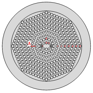

Figure (1): air hole distribution of the proposed O-PCF.
The proposed fiber is fabricated using stack and draw method. At first, it is necessary to create a preform, which is realized by stacking of capillary silica tubes and rods of air hole in order to form the desired structure. After the stacking process, the capillaries and rods are gathered by thin wires and fused together during an intermediate drawing process, where the preform is drawn into preform canes.
Then, the preform is drawn down on a conventional fiber drawing tower, greatly extending its length at temperatures around 2000 °C. Finally, a protective standard jacket, which allows the robust handling of the fibers, surrounds the proposed fiber [15].
- Numerical method
To calculate the guiding proprieties such as chromatic dispersion, birefringence, effective area and confinement loss. Finite element method with perfectly matched layers (PML) is used.
In our simulation, Comsol Multiphysics is used as a simulator to solve the equation of Maxwell’s below [16]:


Here  is the electric field vector, k0 free space wave number, n refractive index of the effective medium, [s] the matrix of the PML layers, [s]-1 is the matrix inverse of [s].
Once the effective index is calculated by the resolution of Maxwell’s equation. The chromatic dispersion, birefringence, effective area also the confinement loss are calculated by the following equation [17]:


 Where Re(neff) and Im(neff) is the real and imaginary part of the effective index
 the wavelength, c the velocity of light in a vacuum, nx and ny are the effective index of each fundamental mode.
To compensate the positive chromatic dispersion caused by the single-mode fiber (SMF-28), the following relationship must be satisfied [18]:


Where  are the dispersion slopes for the single mode fiber (smf-28) and DCF respectively. It is noted that the relative dispersion slope (rds) value of the single mode fiber is about 0.0036 nm-1 at wavelength
  1.55 µm.
- Numerical results and discussion
The electric field distribution for x and y polarization modes is shown in figure (2). At the operating wavelength , it is clear that the electric field of the polarization modes x and y are confined into the core fiber.
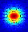
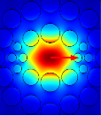
Figure (2).Electric field distribution for x and y polarization modes.
The curve of chromatic dispersion as function of wavelength for the optimum design parameters is shown in figure (3).From figure (3), we can see that the negative chromatic dispersion for the y-polarization mode is larger than the x-polarization mode. The corresponding value of chromatic dispersion are -437 ps/nm/km, -928 ps/nm/km for x,y polarization modes respectively at wavelength  =1.55 µm.
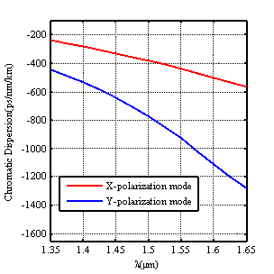
Figure (3).Chromatic dispersion curve as wavelength of the proposed O-PCF for x, y polarizations modes
In our simulation, all calculations will be done for the y polarization mode. In the next part, we study the effect of chromatic dispersion for different geometrical parameters (d, d1, dp,
 ).
).
At first, we calculated the chromatic dispersion for different air hole diameters (d) .For this we kept  0.85 µm, d1=0.5 µm, dp=0.27 µm, =0.68 µm.

Figure (4).effect of the air hole diameters (d) on the chromatic dispersion for y-polarized mode.
From figure (4), in the wavelength range 1.5 µm to 1.52 µm, we can see that the slope of the curves changes significantly when the air hole diameters (d1) change. Moreover at wavelength =1.55 µm, it is observed that the negative chromatic dispersion value increases when the air hole diameters (d1) increase.
The effect of the air hole diameters (d1) on chromatic dispersion is depicted in figure (5) with  0.85 µm, d=0.6 µm, dp=0.27 µm,
  =0.68 µm.

Figure (5).Effect of diameters (d1) on the chromatic dispersion.
From figure (5), at the operating wavelength  =1.55 µm, it is observed that the corresponding value of the negative chromatic dispersion coefficient are -1525 ps/nm/km, -928 ps/nm/km, -830 ps/nm/km respectively for the air hole diameters (d): 0.46 µm, 0.5 µm, 0.54 µm.
Figure (6), shows the effect of the small air hole diameters on the chromatic dispersion. From figure, it is seen that the negative chromatic dispersion coefficient increase when the small air holes diameters increase.

Figure (6).Chromatic dispersion as wavelength for variation of the small air hole diameters (dp)
On the other hand, the effect of the pitch variation is shown in figure (7). From the figure, it is clear that when the pitch ( ) increase the negative chromatic dispersion increase.

Figure (7).Chromatic dispersion variation with pitch ( )
)
Figure (8) shows the chromatic dispersion curves as a function of the wavelength for different pitch value of the small air hole. From figure (8), we can see that all chromatic dispersion decrease when the small air hole pitch  increase.

Figure (8).The effect of ( on chromatic dispersion.
To design a broadband dispersion compensating fiber, it must be that the relative dispersion slope (rds) of the proposed fiber is about 0.0036 nm-1 at =1.55 µm which is exactly to the single mode fiber.For this condition, figure (9) exhibits the dependence of the residual dispersion as a function of the wavelength for the optimum design parameters (0.85 µm, d=0.6 µm, d1=0.5 µm, dp=0.27 µm,  =0.68 µm).

Figure (9).Residual dispersion for optimum design parameters.
As from figure (9), we can see that the residual chromatic dispersion is lower than  64 ps/nm in the wavelength range 1.46-1.675 µm, which confirm that the proposed octagonal photonic crystal fibers could be an excellent device to compensate chromatic dispersion for a 40 Gb/s transmission system over S to U wavelength band telecommunication [19].
According equation (3), figure (10) depicts the variation of birefringence as a function of the wavelength for the optimum design parameters.
As for the figure at operating wavelength =1.55 µm, it is observed that the birefringence is 1.8610-2, which make be used to eliminate the polarization mode dispersion in transmitting data.

Figure (10).Birefringence as wavelength for optimum design parameters.
Figure (11) shows the wavelength dependence on the effective area for the optimum design parameters. At the operating wavelength, the effective area is about 1.7 µm² for y polarization modes. With this value of the effective area, our proposed O-PCF can be used for some application such as supercontinuum and soliton pulse transmission.

Figure (11).Effective area as wavelength for optimum design parameters
Following the equation (5), figure (12) shows the confinement loss variation as a function of wavelength for x, y polarizations modes respectively with optimum design parameters. Of these, it is observed that the confinement loss is about of 0.0012 dB/m, 15 dB/m respectively for the both polarization modes (x,y) at wavelength 1.55 µm. As well as after this operating wavelength the confinement loss increase.

Figure (12).Confinement loss of the proposed O-PCF for x and y polarization modes.
Finally, table (1) displays a comparison between the properties of the proposed fiber with other photonic crystal fibers designed for broadband dispersion compensation at the operating wavelength =1.55 µm.
|
PCF |
D( |
B( |
Aeff (µm²) |
DC Bands |
|
Ref [13] |
-868 |
1.06 |
2.114 |
E,S,C,L |
|
Ref [14] |
-650 |
2.1 |
E,S,C,L |
|
|
Ref [16] |
-294.1 |
2.13 |
2.71 |
E,S,C,L,U |
|
Our proposed O-PCF |
-928 |
1.8 |
1.7 |
S,C,L,U |

 10-2
10-2Table (1).Comparison between the result of the proposed fiber and other works.
- Conclusion
In conclusion, an octagonal photonic crystal fiber is presented as dispersion compensating fiber over S to U wavelength bands telecommunications. Based on stack and draw method, we only used the circular air hole in the fabrication, which shows a high negative chromatic dispersion about of -928 ps/nm/km and a high birefringence 1.8610-2 at wavelength.
This guiding proprieties make our proposed fiber an excellent device for broadband dispersion compensation in high bit-rate transmission networks, sensing application, and so.
References
[1]
[2]
[3]
[4
[5]
[6]
[7]
[8]
[9]
[10]
[11]
[12]
[13]
[14]
[16]
[17]
[18]