Project Design of Portable Stand for Tablet Computer
Â
Â
1.1 Customer Specification
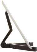
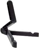
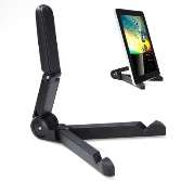
We were approached by a leading computer brand to design a small, lightweight and portable stand that can be used for any of the company’s tablet computers. The company had a strong emphasis on the product being portable and the ability to fit into the end users pocket. The product should allow the end user to easily watch movies, read eBooks, surf the web, conduct a presentation, view photos and much more.
The company would be looking to retail this product at £11.99 and each unit should cost no more than £4 to manufacture. They have also given us 12 months to complete the design with a prototype to be viewed in month 9.
 1.2 Design Specification
After considering the customers specification we began to brainstorm to generate possible solutions. First of all the product is to be small and lightweight which makes the material to be used one of the most important factors. Due to the low production price the stand will be made from ABS plastic resin which can be injection moulded.
The stand will consist of 5 injection moulded parts which are connected by screw pivot barrels. The bottom of the tablet will feature a non-skid cushioned pad which will allow the stand to be used almost anywhere.
- Width (Folded)2.5 cm
- Length (Folded)17.8 cm
- Height (Folded)2.5 cm
- Weight 85g
- No of moulded parts5
 1.3 Safety Considerations
The first point of action is to identify all safety and non-safety critical engineering safety considerations, Customer safety requirements and design safety requirements. For doing this there are many techniques that will be used:
Risk Assessment
Identify hazards– Observe what actually happens and identify hazards that can reasonably be expected to be present. Attention will be taken to any significant hazards which could cause serious harm or affect a number of people. Employees will be asked for their views as they may be aware of hazards which are not immediately obvious.
Who can be harmed? – Everyone should be taken into consideration during the risk assessment, including individuals who may not be present at all times.
Evaluate risk- This will assess the likelihood that harm from a particular hazard may happen whilst also taking into consideration the precautions already in place.
Record findings- Significant findings must be recorded by writing them down. Details of how the assessment was made will be unnecessary. Written documents should be kept for future reference as they may help to demonstrate that legal obligations have been met.
Review and arise- The whole process will be reviewed and new processes or procedures introduced can then lead to new hazards which would result in the need for a new review of all assessments to be carried out to keep them up to date.
Failure Mode and Effects Analysis – FMEA
This analytical technique explores the effects of failures or malfunctions of individual components in a system. This will be the first step of a reliability study. This will involve reviewing all the components and assembly of the stand to identify failure modes and their causes and effects. If any part of the stand fails what will be the result?
The development of the design and testing of the product should ensure that failures have been eliminated or the risk has been reduced to an acceptable level.
Advantages:
- Improve the quality, reliability and safety of the product
- Improve company image and competitiveness
- Increase user satisfaction
- Reduce system development time and cost
- Reduce the potential for warranty concerns
- Early identification and elimination of potential failure modes
- Increases teamwork and idea exchange
- Reduce the possibility of same kind of failure in future
Fault Tree Analysis
This is a graphical technique that will provide a systematic description of the combinations of possible occurrences in a system. This can result in an undesirable outcome. This analysis method will be used to understand how things can fail and to identify the best way to reduce the risk of these happening.
Fault tree analysis will be used to:
- Understand the logic leading to the undesired state
- Show compliance with safety/reliability requirements
- Prioritize the contributors leading to the undesired state/event
- Monitor and control the safety performance
- Minimise and optimise resources
- Assist in the design of the product
- Function as a diagnostic tool
Event Tree Analysis
This will allow us to see what pathway is creating the greatest probability of failure. This is based on binary logic where an event has or has not happened. It is valuable in analysing the consequences arising from a failure or undesired event.
The event tree will begin with an initiating event. The consequences of this event are followed through a series of possible paths where each path will be assigned a probability of occurrences allowing them to be calculated.
Advantages:
- Enables the assessment of multiple faults and failures
- No need to anticipate end events
- Areas of single point failure, system vulnerability may be identified and assessed
- Allows resources to be deployed properly
- Work can be computerized
- Visual cause and effect relationship
- Relatively easy to learn and execute
- Follows easy to see fault paths
- Combines hardware, software, environment, and human interaction
- Permits probability assessment
- Commercial software is available
Â
1.4 Project Schedule
|
Month |
Jan |
Feb |
Mar |
Apr |
May |
Jun |
Jul |
Aug |
Sep |
Oct |
Nov |
Dec |
Jan |
|
|
Problem Identified |
||||||||||||||
|
Initial research |
||||||||||||||
|
Develop Product |
||||||||||||||
|
Build Prototype |
||||||||||||||
|
Testing |
||||||||||||||
|
Redesign |
||||||||||||||
|
Communicate and conclude |
||||||||||||||
Problem Identified– The customer provided us with their specification required for the proposed new product.
Initial research– After Looking over the customer specification research will be conducted to see what products already exist. A brainstorming session will then take place to come up with potential solutions including pro and con lists. From these a best product will then be selected to go ahead and produce.
Develop Product– Once the best possible product has been identified the key requirements for each feature is selected. This will then give and idea of materials needed and how they will construct the tablet. This will then allow costs to be calculated.
Build Prototype– First of all the prototype will be created using CAD software in two and three dimensions. This prototype created in CAD will have all dimensions with tolerances and finishes. This will then be passed onto the production team to construct. This will also be shown to the customer at this stage to ensure it meets expectation.
Testing– Once the prototype arrives it must be tested and evaluated to determine if it works and meets the original customer specification. Minor adjustments may be needed at this point to finalise the design.
Redesign– Using the information gathered during testing, evaluation of the design the solution can then be optimised and revised to achieve better results.
Communicate and conclude – The final product will be shown to the customer before mass production will follow depending on the feedback from the customer.
Â
2.1 Manufacturing considerations.
The prototype was originally modelled using 3d CAD software from where this design was then passed on to the production team to create a solid model of the stand. The prototype did function in the correct manner but the weight was a slight issue. With the product being designed to be portable the weight would need to be reduced. It was decided that the solid components would be hollowed and supports would be set between each side of a component to strengthen them.
The total cost for production has been set not to exceed £4 per unit. The intention is for the stand to be mass produced to decrease product cost and increase profit margin. Due to the small nature of each individual part the best possible way of constructing these will be to use the injection moulding process.
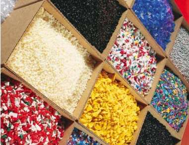
Injection moulding is one of the leading methods of producing plastic components. This is a fast process which is used to produce a large number of identical items. After considering many different materials it was established that ABS plastic resin met all the characteristics needed to form each component whilst also being cheaper than many of the other materials available.
The company’s current injection moulding machine will be used for making the 5 plastic resin components. A 3d model of this is shown below:
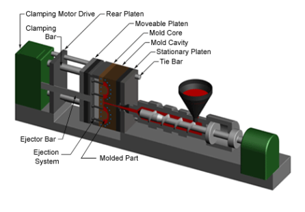
The clamping end with moving platen takes half of the mould tool. This opens and closes the mould and supplies sufficient force to keep the mould closed when molten ABS resin is injected under pressure. The injection unit takes plastic raw plastic resin granules, heats them until molten, and injects them into the mould. The rotating screw forces the plastic along the barrel. When the right amount of material for the next shot has accumulated the screw stops rotating. The screw then acts like a plunger moving forward and forcing the molten plastic into the mould tool.
Materials
There were many different materials that could be used for making the individual parts but after much consideration it was decided that ABS plastic resin pellets would be used. ABS is a thermoplastic resin commonly used for injection moulding applications. ABS (Acrylonitrile Butadiene Styrene) possesses medium strength and performance at a low cost. It is available in multiple grades, colours, and Izod impact ratings.
ABS Features & Benefits:
- Easily machined
- Tough
- Low cost
- Rigid
- High impact strength
- Ideal for moulding
- Good chemical and stress cracking resistance
- Excellent abrasion resistance; electrical properties, moisture and creep resistance.
Availability
At the moment ABS pellets can be purchased from Zibo City Linzi Yixiang Chemical Co. Ltd. In China and shipped to the UK for £1000 per Metric Ton which is 1000000grams. Each rotational part will be held together by 5g pivot barrels also shipped from Asia costing £0.20p per unit.
With each fully built unit weighing in around 85grams and requiring 3 pivot barrels each unit would cost:
1000000/70=14286 units
£1000/14286= 0.6p per unit in ABS material
ABS material + 3 pivot barrels = £0.66p per unit material cost.
This price does not include cost of production.
2.2 Simulation/Modelling
The design process will utilize the use of CAD to produce the trailers drafting and design. By using CAD this will allow the quality of the design to be improved whilst also speeding up the design process. The drafted design of the trailer will be used by any professional involved in the construction of the trailer. 3d simulation also allows for real life situations to be tested prior to the build.
Advantages and disadvantages of using CAD
Advantages
- Can be more accurate than hand-drawn designs which reduce human error.
- You can save and edit ideas, which make it easier and cheaper to modify your design as you go along.
- You can modify existing ideas, which saves time.
Disadvantages
- The software itself can be expensive so initial costs are high.
- Staff need to be trained how to use the software, which also adds to costs.
- Requires a PC.
- Safety Considerations
Although the product is fairly small and compact there are still many safety issues that need to be taken into consideration. Legislation should also be adhered to. Plastic materials are generally inert and lend themselves to product safety. The safety of plastic materials and products which will be used by users and consumers is extremely important to the company and to the industry as a whole. The cost problems associated with exercises such as product recalls and product failure could have a negative image on the company.
The risk assessment technique used for tablet stand was a Fault Modes and Effects Analysis (FMEA). This method will explore the effect of malfunctions and failures for the individual parts of the product whilst also looking at what can happen within the working environment.
The essential questions which are asked in regards to the working environment are:
- What are the hazards?
- Who could be harmed and how?
- What are the effects?
- What is currently done?
- Can anything else be done?
|
What are the hazards? |
Who can be harmed and how? |
What’s being done? |
What can be done? |
|
Slips and trips |
Staff/contractors may be injured if they trip over objects or slip on spillages. |
â- Procedures for oil spillages in place and are adhered to â- Floors are in good condition â- Staff wear safety shoes â- Good lighting throughout |
No further action required |
|
Use of injection machinery |
Staff/contractors may suffer serious injury from unguarded moving parts of machinery |
â- All dangerous parts of machinery guarded to manufacturers’ standards â- All new machinery checked before first use â- Machinery guards are properly maintained and inspected |
No further action required |
|
Workplace transport |
Staff may suffer serious, fatal, injuries if struck by a vehicle or fork lift truck. |
â- Good segregation measures are on site, â- All staff, including contractors, wear hi-visibility work wear â- Annual safety inspections |
Provide safety rules before jobs begin |
|
Manual handling |
Staff may suffer back pain from handling heavy/bulky objects. |
â- Staff are trained in safe manual handling â- Safe system of work agreed â- Manual handling aids are |
No further action required |
|
Fire |
Staff could have fatal injuries from smoke inhalation or burns. |
â- Fire risk assessment had been previously done, and any necessary action taken, â- Staff and contractors told of fire and evacuation policy |
No further action required |
|
Noise |
Staff may suffer discomfort and potential hearing damage if working in noisy areas or using noisy equipment. |
â- If possible, jobs in production areas done when the injection moulding machines are not in use â- Staff provided with ear defenders or suitable hearing protection when required â- Machinery is maintained to ensure they run as quietly as possible |
No further action required |
The essential questions which are asked in regards to the product are:
- How can each part fail?
- What might cause this failure?
- What will the effects of failure be?
- How serious are these failures?
- How are the failures detected?
|
Component |
Potential Failure |
Potential effects of failure |
Severity |
Potential causes of failure |
How will failure be detected |
Action to control risk |
|
Plastic Parts |
Breaking |
Unusable and possible tablet breakage |
II |
End user misuse |
Visual |
Instructions provided |
|
Plastic Parts |
Melting |
Product wont function |
II |
End user misuse |
Visual |
Instructions provided |
|
Plastic Parts |
Wear and tear |
Unstable |
I |
Overuse |
Visual |
Warranty |
|
Plastic Parts |
Causing harm |
End user harm. Potential Legal issues |
III |
Finishing |
Visual |
Instructions provided |
|
Pivot Screws |
Breaking |
Unusable and possible tablet breakage |
II |
End user misuse |
Visual |
Instructions provided |
|
Pivot Screws |
Wear and tear |
Still usable but not 100% |
I |
Overuse |
Visual |
Warranty |
The level of risk is determined by: Risk = probability of failure * Severity factor
|
Severity Categorised |
||
|
Category |
Probability |
Description |
|
I |
Minor |
Functional failure of part of machine or process – no potential for injury |
|
II |
Critical |
Failure will probably occur without major damage to system or serious injury |
|
III |
Major |
Major damage to system and/or potential serious injury or personal |
|
IV |
Catastrophic |
Failure causes complete system loss and/or potential for fatal injury |
|
Probability Categorised |
|||
|
Level |
Probability |
Individual failure mode |
|
|
A |
10-1 |
Frequent |
Likely to occur frequently |
|
B |
10-2 |
Probable |
Likely to occur several times in the life of the product |
|
C |
10-3 |
Occasional |
Likely to occur sometime in the life of the product |
|
D |
10-4 |
Remote |
Unlikely to occur but possible |
|
E |
10-5 |
Improbable |
So unlikely that occurrence may not be experienced |
|
|
|
RP1 |
High Risk |
|
|
RP2 |
||
|
C |
RP3 |
Medium Risk |
|
|
D |
Low Risk |
||
|
E |
|||
|
I |
II |
III |
IV |
 A
A
 B
BSeverity Category
Legislation
The company currently adheres to ISO 9001:2008 for the plastic sector which aims to improve the efficiency of all operations within the sector, whether in manufacturing or distributing.
2.4 Details of the final design


3.1 Product Evaluation.
When evaluating the design there are a wide range of methods and strategies. The one used in this instance is:
F.A.C.E. value
Function – What does it do and how does it work?
Aesthetics – Is it attractive, why and what makes it so?
Construction – What is it made from, how and why?
Economics – How much does it cost and is this good value for money?
Function: The stand will hold a number of current products in landscape or horizontal position for ease of use.
Aesthetics: The product was never designed to be good looking but functional.
Construction: The product was eventually made from ABS plastic resin due to its properties and cost. The constructed parts are held together with pivot screws due to their cost and ease of use.
Economics: The customer had given us a maximum price to work too which enabled us to use strict guidelines when it came to purchasing products. Most of the materials were imported from China due to price issues. Although the product may seem good value money from our point of view, this may not be replicated by the end customer.
3.2 Team Working.
Although everyone was not capable of working within a team, the selected group which were proved that teamwork has many benefits. The team worked more efficiently and speed was also increased compared to individual workers. This method also offered support for any members’ ideas.
Creativity Increases:
The group brainstorming activity process provided incredible results. Everyone came up with their own vision of the best way of creating the product to the customer needs. The team then decided which idea was the best and then continued to develop this in detail together. This was an invaluable process where team members could give instant feedback on what they thought what would and wouldn’t work.
Speed:
Individuals have different strengths and weaknesses. When it came to tackling the project together the team delegated the workload among themselves according to each other’s skills. This no only saved time but it also allowed distribution of work within the team ensuring everything was done in the best possible way.
Effect on Worker Morale:
As staff members were working closely together as a successful team, they spend more time together and begin to know each other. This then created a good relationship between the employees. They started to feel proud of what they had achieved ad contributed to the project which also made them feel good about themselves. This seemed to help their self-esteem.
Effect on Individual Responsibility:
The overall product was produced by teamwork; all the team members felt they had to deliver to their highest abilities. Everyone had a clear understanding that they were responsible for a specific task and the entire team was depending on them doing a good job.
3.3 Evaluation of Safety
During the design process safety was one of the main aspects to consider. Many materials were considered but due too certain aspects whether it was finishing or the product being fire retardant. ABS was eventually picked as this would reduce risk in the overall design of the product. The risk assessments carried out for the workplace proved invaluable as this gave the company a clear indication of what was currently being done within the working environment and what could still be done to improve the safety.