Reverse Engineering (Sequence Diagrams)
Keywords- Sequence diagrams, reverse engineering, execution traces.
UML helps software engineers understand software through the visualization of interaction of the objects with other objects in it. When sequence diagram is absent the reverse engineering is used to extract accurate models. As per the paper, the authors have taken into account that RE (reverse engineering) of SD from extraction traces of object-oriented systems. The definition of execution trace can be given as a sequence of method invocations where each invocation represents interaction among objects. Reverse engineering can be done in two ways, one by analyzing the source code if the system statically and the other is to dynamically executing the program and analyzing the resulting traces for the sequence diagrams.
Here, we are considering the method of execution traces of object-oriented systems for the reverse engineering of sequence diagram. Sequence of method invocation that shows the communication of different objects in an object-oriented system is known as an execution trace in that system. There are two challenges while mapping the traces of method invocation and messages which are:
- Control flow detection.
- Multiple execution trace merging.
Existing methods use static analysis if method invocation is linked to loop blocks in source. Even though this solution cannot be used in the absence of source code. Several other methods have been proposed to cope with the above two challenges in reverse engineering, but they work only with sequence diagram that too from a single trace and the outcome with multiple execution trace is still uncertain.
The prime goal here is to get the UML sequence diagram from multiple traces of execution using only dynamic analysis. Here, before going ahead towards the approach first the model which is used for formalizing the reverse engineering of UML designing is presented.
A. Execution traces:
First, the analysis is done by observing the trace of execution of the respective system. It can be defined as a sequence of method invocations. [1] Then invocation of methods and traces are defined as: label. caller | method | callee.
Trace: Trace is just a sequence of invocation of methods.
B. Sequence diagrams
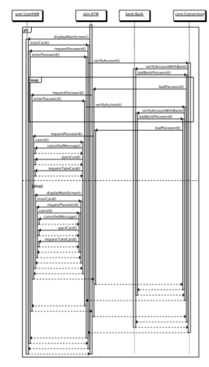
A sequence diagram shows the interaction of objects in a system with each other. It can also be shown as an algebraic expression with method invocation as atomic terms an the three operators as the operator in the expression.
Sequence diagram can be expressed as[1]:
D::=M|(DaltD)|(DseqD)|loop(D)
This approach consosts of the following steps:
- Collection of traces.
- Merging of traces.
- Extraction of sequence diagrams.
Collection of traces: In the first step, the interaction is observed of objects which are known, in different situations. Every situation, a method invocation is created and an execution trace is captured.
Merging of traces: In this step, based on LTS merging, a technique is used which is described in the next section in detail.
Extraction of sequence diagrams: In the last step, a sequence diagram is generated with the results of the previous steps
Here the K-tail algorithm is used also known as grammar inference technique for merging execution traces. This involves two steps, which are as follows:
- Initialization: Here a LTS is generated for every execution trace. The generated LTS is a version of the finite automata.
- Merging: Here the above mentioned algorithm is applied for the merger of LTSes of different execution traces into one LTS.
This algorithm uses the initial transitions systems as input, then merges K-equivalents. If the obtained states can be defined by the same path of method invocation, then only they can be considered as “K-equivalent”.
The obtained LTS here shows the behavior in the input traces.
In this part an approach is presented to extract a sequence diagram generated by the k-tail algorithm. As per the approach, known solution are reused for transforming DFA to Regular Expression for obtaining Regular Expression equivalent to LTS. The resultant Regular Expression is converted to sequence diagram through simple mapping.
An approach has been proposed in the research for the reverse engineering of SD which is based on dynamic analysis. This approach is considered to be very important because in some secured systems, source code might not be provided.
We have used the K-tail algorithm for the extraction of Labeled transition systems (LTS) from observed execution traces. Later the extracted LTS is converted into a SD and then after mapping to a regular expression.
RE- Reverse Engineering, SD-Sequence diagram, LTS- Labeled Transition System, RE2 – Regular Expression.
[1] Tewfik Ziadiâˆ- , Marcos Aurélio Almeida da Silvaâˆ- , Lom Messan Hillahâˆ-†, Mikal Ziane “A Fully Dynamic Approach to the Reverse Engineering of UML Sequence Diagrams.”, âˆ-UMR CNRS 7606, LIP6-MoVe Université Pierre et Marie Curie, Paris, France †Université Paris Ouest Nanterre La Défense, Nanterre, France ‡Université Paris Descartes, Paris, France.
[2] Lionel C. Briand, Senior Member, IEEE, Yvan Labiche, Member, IEEE, and Johanne Leduc “Toward the Reverse Engineering of UML Sequence Diagrams for Distributed Java Software”, IEEE TRANSACTIONS ON SOFTWARE ENGINEERING, VOL. 32, NO. 9, SEPTEMBER 2006.

Fig. 1 An example of extracted sequence diagram