Superstructure Preliminary Design Report
Two superstructure design options for the warehouse have been considered and discussed for the chosen layout, for the first design which is a portal frame and the other is a trusses structure. And all the materials were used in steelwork which are in S355.
Design option one
- For this design option, simple portal frame are used as the main structural design and the frame contains 10 bays, each of them are 6m wide and 17m total length. This give a total area of 102m2 per bay which is satisfy the minimum requirement of the bay area of 85m2 at the beginning of the design brief. The height of the top of the column is 6m and the highest point of the roof is 6.9m which is using 6 degrees for designing the portal frame and which is satisfies the minimum floor to ceiling height of 6m at the beginning of the design brief as well.
- For the Section sizing, Loading calculations have been completed, and a size for each member has been chosen based on the loads acting on the structure. For the rafter, all secondary beams, (this includes the beams between columns, and the ridge beam), a section size of 356x171x45 UKB has been chosen. It has been assumed that the columns are unrestrained; this choice may be revised in the future. Under this assumption, along with the loading conditions, a section size of 533x210x22 UKB has been chosen for each column.
- Moreover, the diagonal cross spacing was used for the bracing design in order to maintain the stability of the whole structure under the wind loading and has been sized by using the load calculation conditions, a section size of 60x60x8 UKA has been chosen for all bracing on the roof. Furthermore, haunches with 10% of the span of the rafter long which to touch between each column and the corner of the rafter which mainly use to obtain the effect of hogging.
Advantages:
- The main braces of the structure located on the roof of the portal frame that gives more cavity in between columns. In other words, it gives more options for the locations of the gates for the lorries to drop off. On the other hand, more fire exit can be set.
- As the roof make angles with both front and side of the structure, the brace on the roof can undertake wind pressure in both directions. In which, less brace is held in front and side of it. This cost less time and cost to construct.
- The whole structure is design to make with steel beams. This gives the structure with higher strength compare with concrete beams and columns.
- Between columns and columns, they have equal spaces. This led them to share the same amount to compression. The columns will share the same displacement during deformation. Easier approximation while the structure collapses.
- As each portal frame share the same structure, it spends less time to construct.
- Pin joints are used as the support on the bottom of each columns instead of fixed support, the columns of the structure undergo lesser banding moments.
- A vertical brace is held on the last part of the structure, it supports the brace on the roof. In other words, the materials use to make brace on the roof can be reduced.
- Two extra columns have been placed at both ends of the portal frame in order to support the end-span, as both end-spans do not have secondary beams either side to help stabilise the rafters in these sections.
Disadvantages:
- While the main braces are on the top of the roof, the columns have to support higher load.
- The only vertical brace may block the space in between the columns. The main entrance may have to move.
Design option two
- The second design option utilises a Pratt-pattern truss between the columns of each bay to replace a rafter with a haunch. Same as the first design, the frame contains 8 bays, each 6m wide and with a total length of 17m; giving a total area of 102m2 per bay which is satisfy the minimum requirement of the bay area of 85m2 at the beginning of the design brief. The height of the top of the column is 6m and the highest point of the roof is 6.9m which is using 6 degrees for designing the portal frame and which is satisfies the minimum floor to ceiling height of 6m at the beginning of the design brief as well.
- This design has no bracing as the truss can be afford for the lateral load to maintain the stability of the structure, attained from the use of a truss is sufficient enough to invalidate the use of bracing elsewhere in this particular design. Two extra columns have been placed at both end trusses in order to support the end-span, as both end-spans do not have secondary beams at either side of the truss to help stabilise them. The struts in the trusses are to be connected to the tie beam and rafter using gusset plates and bolts; and the bracing attached to the rafters using the same method.
- For the Section sizing, Loading calculations have been completed, and a size for each member has been chosen based on the loads acting on the structure. For the rafter, all secondary beams, (this includes the beams between columns, and the ridge beam), a section size of 356x171x45 UKB has been chosen. It has been assumed that the columns are unrestrained; this choice may be revised in the future. Under this assumption, along with the loading conditions, a section size of 533x210x22 UKB has been chosen for each column.
Advantages
- The design has large amount of trusses set on top of the structure. It can from the side of the structure.
- The whole structure is design to make with steel beams. This gives the structure with higher strength compare with concrete beams and columns.
- As no vertical brace with the structure to the bottom, this allow extra lorry loading gates. Other than that, flexible fire exits can be set.
- Equal spacing within columns and columns, this lead to share the same amount to compression. The columns will share the same displacement during deformation. Easier approximation while the structure collapses.
- Pin joints are used as the support on the bottom of each columns instead of fixed support, the columns of the structure undergo lesser banding moments.
Disadvantages
- As the trusses held on the top of the structure, it gives extra load on the column. Thicker columns have to be used.
- The cost is relatively high due to the following reasons:
-Lot of connections with that trusses
-More materials are used
-More complied structure, harder to construct
- While space on the upper part uses as trusses, lesser goods can be stored, it           may decrease the efficiency of the portal frame.
- Construction is time consuming as it has complicated structure.
The calculations of the initial loading input
Basic values
Determine the basic wind velocity
(For simplification the directional factor cdir and the seasonal factor cseason are in general equal to 1.0)

 2
2 
Basic velocity pressure
Where 
 2
2
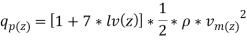
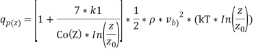
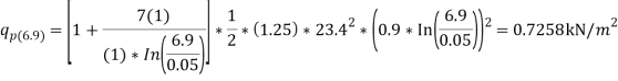
Peak Pressure
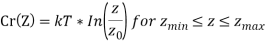
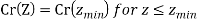
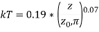
          Calculation of  = (mean wind velocity)
          Where  ,
, 
2 


Calculation of  turbulence intensity
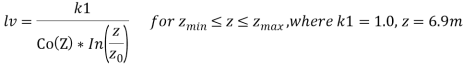
 (
(
So,

|
Imposed load |
Wind load(0 degree) |
Roof cladding, insulation and services |
Snow load |
UKC 533x210x92 (Unrestrained column) |
UKB 356x171x45 (Rafter& secondary beam) |
UKA 60x60x8 (bracing) |
|
|
magnitude |
0.6 |
0.871 |
1.5 |
0.6 |
92 |
45 |
7.09 |
|
unit |
kN/m2 |
kN/m3 |
kN/m2 |
kN/m2 |
kg/m |
kg/m |
kg/m |
|
length |
4.8m |
4.8m |
4.8m |
4.8m |
6m |
8.5475m |
10.443m |
|
Initial load |
2.88 kN/m |
4.181kN/m |
7.2kN/m |
2.88kN/m |
5.41512kN |
0.44145kN |
0.06955kN |
|
Combination |
Variable |
Variable |
Permanent |
Permanent |
Permanent |
||
|
Properties |
Unfavorable |
favorable |
|||||
|
characteristic values 1 |
1.5 |
1.5 |
1.1 |
1.5 |
1.1 |
0.9 |
1.35 |
|
characteristic values 2 |
1.5 |
1.5 |
1.35 |
1.5 |
1.35 |
1 |
1.35 |
|
characteristic values 3 |
1.3 |
1.3 |
1 |
1.3 |
1 |
1 |
1.5 |
|
Total load 1 |
4.32 kN/m |
6.270912 kN/m |
7.92 kN/m |
4.32kN/m |
5.956632 kN |
0.397305 kN |
0.093896415 kN |
|
Total load 2 |
4.32 kN/m |
6.270912 kN/m |
9.72 kN/m |
4.32 kN/m |
7.310412 kN |
0.44145 kN |
0.093896415 kN |
|
Total load 3 |
3.744 kN/m |
5.4347904 kN/m |
7.2 kN/m |
3.744 kN/m |
5.41512 kN |
0.44145 kN |
0.10432935 kN |
All the load calculation was took the total load 2 which got the largest value for the worst case.
The approximate price calculations for both designs
Design 1
The following table shows the materials used of the design;
|
Size of steel |
Length(m) |
Quantity |
Usage |
|
UB 533x210x92 |
6 |
22 |
Column |
|
UB 356x171x45 |
8.54751 |
22 |
Roof |
|
UB 356x171x45 |
4.8 |
30 |
Roof |
|
UA 60x60x8 |
9.8 |
40 |
brace |
|
UA 60x60x8 |
7.68375 |
4 |
brace |
Total weight:
|
Size of steel |
kg/m |
Total length(m) |
Total weight |
|
|
UB 533x210x92 |
92.1 |
132 |
12157.2 |
|
|
UB 356x171x45 |
45 |
332.04522 |
14942.0349 |
|
|
UA 60x60x8 |
7.089 |
536 |
3799.704 |
|
|
Total weight of steel =30900kg= 34ton |
||||
Assuming price of steel is £700 per ton, cost of the steel used = £23800
Other than that, joints within the structure are also coincided.
|
M16 bolts in each joint |
Number of joints |
Total number of M16 bolts |
|
8 |
140 |
1120 |
Assuming price of each M16 bolt is £2, cost of bolts used =£2240
Total cost of the structure is around £26040
Design 2
|
Size of steel |
Length(m) |
Quantity |
Usage |
|
UB 533x210x92 |
6 |
22 |
column |
|
UB 356x171x45 |
4.8 |
40 |
Truss |
|
UB 356x171x45 |
1.7 |
110 |
Truss |
|
UB 356x171x45 |
8.6 |
22 |
Truss |
|
UB 356x171x45 |
2.3 |
22 |
Truss |
|
UB 356x171x45 |
2.4 |
22 |
Truss |
|
UB 356x171x45 |
2.5 |
22 |
Truss |
|
UB 356x171x45 |
2.7 |
22 |
Truss |
|
UB 356x171x45 |
2.8 |
22 |
Truss |
|
UB 356x171x45 |
1.7 |
22 |
Truss |
|
UB 356x171x45 |
1.9 |
22 |
Truss |
|
UB 356x171x45 |
2 |
22 |
Truss |
|
UB 356x171x45 |
2.2 |
22 |
Truss |
|
UB 356x171x45 |
2.4 |
11 |
Truss |
|
Size of steel |
kg/m |
Total length(m) |
Total weight |
|
UB 533x210x92 |
92.1 |
132 |
12157.2 |
|
UB 356x171x45 |
45 |
1045.6 |
47052 |
Total weight of steel = 59200kg =65.26 ton
Assuming price of steel is £700 per ton, price of the steel used = £45700
Other than that, joints within the structure are also coincided.
|
M16 bolts in each joint |
Number of joints |
Total number of M16 bolts |
|
8 |
242 |
1936 |
Assuming price of each M16 bolt is £2, cost of bolts used =£3872
Total cost of the structure is around £3872.
End of paper