Supplementary Restraint and Air-bag system
Supplementary restraint and airbag system is a passive part of vehicle safety system. SRS is designed to protect and lower forces acting on the driver and passenger at the event of the accident. In a case of an accident at speed about 35km/h the SRS is activated and the following procedure is taking place:
-seat belt tensioners are activated -about 10-15 ms
-airbags are inflated -about 10-40 ms
-airbags are deflated -40-120 ms driver or passengers kinetic energy is taken in by airbags
-around 120 ms after accident the airbags are deflated
SRS and air-bag system consist of:
-Driver and passenger airbags (including igniter and pyrotechnic inflator)
-a warning light (MIL)
-seat belt pretensioners
-impact sensors (crash sensors)
-electronic control unit.
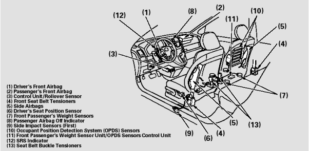
Illustration 1. SRS
Driver and passenger airbag
The airbag is made of one side coated nylon and has a shape of a big cushion. To allow rapid deflation air bag has side holes. Airbag is placed into steering wheel (driver) and front of passenger side but also is placed on the both sides inside of the car as a curtain (protecting against side impact). In the modern car the number of airbags and their sizes are constantly changing, but principals are the same.
In a case of an accident ECU engage igniter which triggers the spark necessary to burn fuel tablets (pyrotechnic inflator). The burned fuel tablets produce a nitrogen gas which inflates the airbag. Everything happens in few ms and the amount of gas and pressure created during burning is strictly calculated for each airbag.
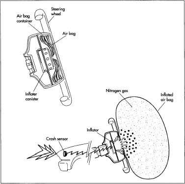
Illustration 2. Airbag
Warning Light (MIL)
A warning light is used as a part of the self-diagnostic system. Every time when the ignition is switched on SRS checks all components of the system and if any fault appeared the MIL is activated. MIL light stays on as long as the problem of the system is not rectified.

Illustration 3. MIL Warning Light
Seat belt tensioners
The function of the seat belts is to secure occupant of the vehicle from injuries at an accident or a sudden stop. Due to a seat belt slack, belt stretch, three point seat belt protection is limited up to 40 km/h, if speed is higher than this limit the occupant’s head or body can impact the steering wheel or the instrument panel.
Seat belt pretensioners improve restraining ability of the seat belt and increase the protection of the occupant from injuries. In modern cars there are two types of tensioners, both of them can work simultaneously. The first type is a shoulder pretensioner. The pretensioner pulls the seat belt tighter and holds the occupant closely to the seat’s backrest. This action prevents the body from excessive forward movement. The pretensioner is activated at around 10-15 ms, and by conjunction with an airbag (10-50ms fully deployed) they absorb kinetic energy acting on the body. When the supplementary restraint system (SRS) detected an accident the pyrotechnic propellant charge placed in the tube tightener is activated and pressure is created. The rising pressure in tightener pushes the piston which is attached to the steel cable and pulls the seat belt tightly against the occupant.

Illustration 4. Seat belt pretensioners
In addition to the shoulder belt tensioner a buckle tighteners are developed. The buckle tensioner improves the restraining and protection on the occupant and prevents the body from submarining.
Impact sensors
There are two types of impact sensors: mechanical and electronic. The mechanical system is a “ball in tube” mechanism which basically consists of a ball, tube, magnet (holding the ball in position) and electrical circuit with a switch. If an accident occurs the ball is dislodged from the magnet and starts to roll forward inside the tube closing the circuit switch. Then the signal is sent to ECU to take further action.
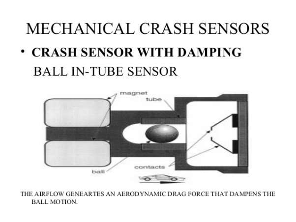 Illustration 5. Mechanical crash sensor
Another type is an accelerometer. This kind of sensor detects any changes in a speed of a car and there are a few types of them in use.
One of them is a piezoelectric crystal accelerometer which works on principals similar to the engine knock sensor, another one uses a spring. A drastic change in car speed (deceleration) will cause the seismic mass movement or a spring bend, either of which will then change the output from these sensors. Main advantage of this type of sensor is that sensors don’t have to be designed for each car separately, as all changes can be made by the software.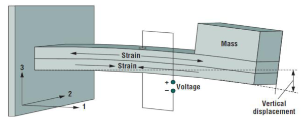 Illustraton 6. Electronic crash sensor
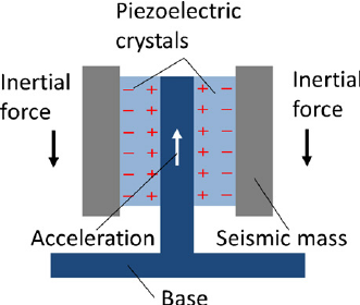
Illustration 7. Piezoelectric crash sensor
Electronic central unit (ECU)
Electronic central unit collects and analysis the data from sensors and according to them it takes further action. The ECU has following functions:
-crash sensing by crash sensors (acceleration sensors)
-prompt activation of airbags and seat belt tensioners according to different types of the impact in the vehicle longitudinal direction eg. rear-end, frontal, side
– triggering of the seat belt tensioners depending on the buckle status, firing only when buckle is fastened
– voltage and energy accumulator if vehicle battery fails
-diagnosis of external and internal system components
-MIL activation
-storage of faulty codes and duration of it
-watchdog (WD) constant monitoring of the airbag units with regards to false activation in non-crash situation and corrected if needed. Since 2003 all ECU has three independent monitoring hardware watchdogs: WD1, WD2 and WD3. Each of them independently monitor the system and if all data collected by them is matching the system is triggering procedure according to situation.
Â
Diagnosis and repair defect:
Make: Vauxhall
Model: Astra
Year: 2008
Reg. No: NL08BYY
VIN: WOLOAHL0885070200
After switching on the ignition the Airbag MIL appeared on the dashboard. To find out the faulty code I plugged in the Snap-on diagnostic tool. Codes B0012 (driver airbag open circuit stage 1) and B0013 (driver airbag open circuit Stage 2) appeared.
My diagnosis: there is no connection between the airbag unit and the system.
To rectify this fault I do as follow:
-battery disconnected for at least 10 mins
-removed air bag from the steering wheel
-diagnosis confirmed: airbag was disconnected from the circuit
-Two plugs were connected to the airbag according to the number placed on the airbag
-air bag was replaced on the steering wheel
-battery was connected
Finally, to confirm my diagnosis I reconnected the Snap-on diagnostic tool and erased faulty codes. MIL went off and the codes disappeared from the system.