Three Phase Systems
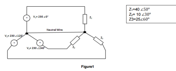
Determine the neutral current in the unblanced 4-wire star power system shown in figure1. Express the answer in both complex number and polar forms.
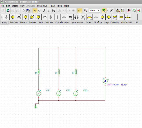
Use a simulator to confirm the magnitude of the nuetral current which is eqaluated.
Given that,
Z1 = 40 ∠50°
Z2 = 10 ∠30°
Z3 = 25 ∠60°
V1 = 230 ∠0°
V2 = 230 ∠120°
V3 = 230 ∠240°
 To Find Neutral Current by Calculation:
To find the neutral current, first we have to find I1, I2 and I3 and then add them together to get the neutral current.
 To find I1:
I1 = 
I1 = 
 I1 =
I1 = 
 –
– 
I1 = (5.75  –
–  ) A       (Polar Form)
 Current in Rectangular Form:
I1 = (3.69 -j 4.40) A
 To find I2:
I2 = 
I2 = 
 I2 =
I2 = 
 –
– 
I2 = (23  90
90 ) A       (Polar Form)
 Current in Rectangular Form:
I2 = (0 +j 23) A
 To find I3:
I3 = 
I3 = 
 I3 =
I3 = 
 –
– 
I3 = (9.2 180) A       (Polar Form)

I3 = (-9.2 +j 0) A           (Rectangular Form)
Now to find neutral current IN, we need to add I1, I2 and I3
IN = I1 + I2 + I3
IN = (3.69 -j 4.40) + (0 +j 23 ) + (-9.2 +j 0)
 IN = (3.96 + 0 – 9.2) +j (-4.40 + 23 + 0)
IN = (-5.51 +j 18.6) A          (Rectangular Form)
IN = 19.39 106.50 A       (Polar Form)
 Using TINA Simulation:
Use the three-wattmeter method on a simulator to determine the total effective power dissipated in Figure1. Confirm this answer by calculation.
 Using TINA Simulation:
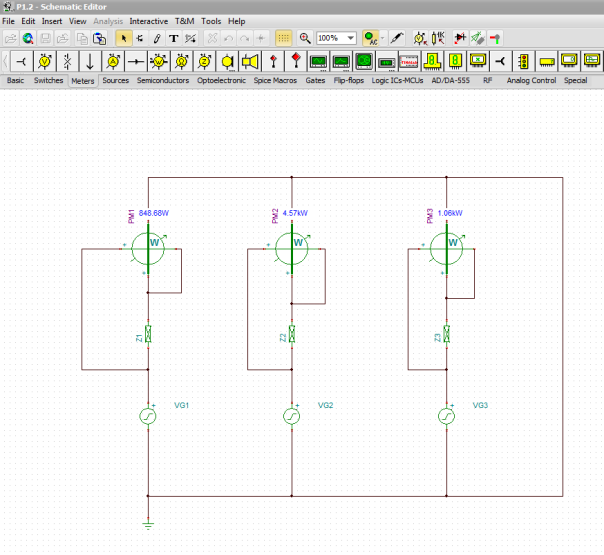
 Total Effective Power Dissipated in Figure1 by Calculation:
To find total effective power dissipated, first we have to find P1 eff, P2 effand P3 eff
 To find P1 eff :
P1 eff 
 P1 eff =
  cos 50
P1 eff = 850 W
 To find P2 eff :
P1 eff 
 P2 eff =
  cos 30
P2 eff = 4581.27 W
 To find P3 eff :
P1 eff 
 P1 eff =
  cos 60
P1 eff = 1058 W
P total = P1 eff + P2 eff+ P3 eff
 P total = 850 + 4581.27 + 1058
P total = 6489.27 W
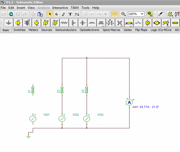
If V1 went open circuit, calculate the new value of neutral current for Figure1.
if V1 went open or is at fault then I1 will become zero and the neutral current will be the sum of the other two currents I1 and I2
IN = I1 + I2 + I3
V1 went open so, I1 = 0 therefore,
IN = 0 + I2 + I3
IN = I2 + I3
IN = (0 +j 23) + (-9.2 +j 0)
 IN = (0 – 9.2) + j (23 + 0)
IN = (-9.2 + j23) A              (Rectangular Form)

IN = 24.77 111.80 A      (Polar Form)  ÂÂ
Single-core Three-Phase Double-Wound Transformer
 Introduction:
Transformer is a static device which transfers electrical energy or power between two or more than two circuits using phenomena of Electromagnetic induction. It takes the current of one voltage and converts it into a different voltage. The amount of transferred energy from Primary circuit to the Secondary Circuit is equal, and the losses are ignored. The frequency of the circuits does not change but the voltage and current of each of the individual circuit is changed, it is increased or decreased, unless we use the transformer as a one-to-one isolating transformer.
Basically, the transformer perform the function of changing electricity from high to low voltage by making use of the following properties of electricity.
- Magnetism is always present around in an electric circuit.
- Magnetic field is always changed by changing the strength or moving the conductor therefore voltage is induced.
Voltage is known as the measure of the “Force” or “Pressure” that is used to push the electrons around the circuit.
Electricity at a higher voltage goes in the transformer and runs through the large number of coils that are wounded around the iron core. As the current is changing, the core magnetism will also be changing. A wire with less coils around the iron core is known as the output wire and the changing magnetism produces current in the wire. When the number of coils are less that means less voltage and more coils means more voltage. Therefore, the voltage is either stepped down or stepped up according to the number of coils in the wire.
A common transformer involves a ferromagnetic core which ensures that values of magnetic flux linkage remain high. But there are some factors related to the ferromagnetic materials that are responsible for part of the loss associated with power transfer. These losses are as follows:
1. Core losses:
Core losses can be classified as the sum of eddy currents losses and the hysteresis loss.
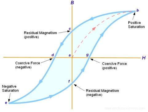
- Hysteresis loss:
Energy that a magnetic material soaks in cannot be recovered completely. Core of the material is excited by an A.C source, the flux density rises and falls with the magnetic field strength or current which is basically sinusoidal. When the magnetizing current increases the flux density also increases but there comes a point after which if there is any further increase in the current, flux density is saturated. If the current is reduced from the saturation point to zero, flux density will start to decrease. When the value of the current reaches upto zero the flux density should also become zero but it does not become equal to zero. Some of the flux density will still be present in the material for the zero current, which is called as a residual magnetic flux. Thus, the total amount of energy used to magnetize the material cannot be recovered back and this energy is trapped within the material core and is dissipated as a form of heat. Area of B/H curve gives the hysteresis loss, larger the loop the greater the energy required to create the magnetic field.
- Eddy current losses:
If a coil is wrapped around a core made up of some material and an A.C source is applied to circuit, eddy current losses take place. As the supply to the coil is changing or alternating which produces an alternating flux in the coil. The varying flux in the core induces e.m.f in the core material due to which eddy currents start to flowing in the core material. Therefore, the energy is lost or dissipated in the form of heat because of eddy currents.
The laminations in the core can reduce the eddy current losses. Thin sheet steels which are separated from each other must be used because these insulated sheets reduce the amount of the current flow and hence the eddy current losses.
2. Copper losses:
Copper loss occurs when the transformer is loaded, the input power is dissipated as heat in the primary and secondary windings of the transformer because these windings have internal resistance. When the load is low, the amount of heat produced is small but at high loads the amount of heat produced becomes significant.
ï‚· Construction of Single-core three-phase double wound Transformer:
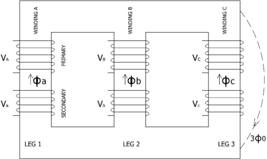
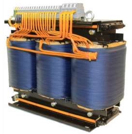
A single-core three-phase double wound transformer consists of three sets of primary and secondary windings, individual set winded on each leg of the core made up of iron. The windings consists of turns made up with the insulated wire. These coils are then mounted on a magnetic core material in such a way that the magnetic flux produced by one coil increases and ensures that the most of the magnetic flux links with the second coil so that mutual induction is being increased. The coils are spaced 120 degrees apart. The transformer is filled with a dielectric oil and thus provide insulation in-between the winding and case. These windings are either connected in star or delta configurations.
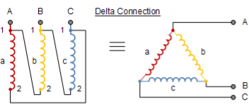
- Delta Connection:
Delta system proves excellent for distribution system for short distances. These types of transformers are used in neighbourhood and commercial loads of small magnitude near to the substations. There is one kind of voltage present between the 2 wires in the delta system. This system is shown by a Triangle. The voltage between any two wires will be the same and from each individual point of the Triangle, wire emerges which represents a three phase.
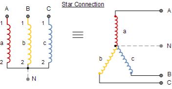
- Star Connections:
For a star connection, voltage of two lines is the same as the voltage on a 3 phase system. In Star connection, each of the windings are made up connecting each individual winding end to end and this point is the “star point” or “neutral point” of connection winding. Connection for neutral and 3 phase connections are then taken out of transformer.
ï‚· Applications of Transformers:
- Transformers in Electrical Engineering:
An electrical engineer may put a transformer in a circuit for many reasons. If the device being powered require higher power than what is available locally or the powered device needs frequency matching, a transformer is placed in such circuits. For example signal and audio transformers are used to couple amplifiers and microphones to the input of the amplifiers.

- Power Utilities:
When driving through a rural area, power polls and overhead power lines can be seen and transformers are placed on these power polls by power utilities. Utility substations make use of transformers to deliver power of certain usable level and quality to consumers and businesses.
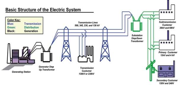
- Power Generation and Distribution:
Electrical power is generated at the power station and this electrical energy is then transferred to the consumers through high tension power lines. To distribute the electricity from the power station to the consumer, different transformers are used in stepping up and stepping down the voltage up to the certain level.
- Commercial use:
Every electrical device uses transformer in one way or another. Almost every commercial building has at least three or four large high power transformers in order to provide required voltages to operate overhead lightning system, telephone system, heating, operating electrical equipment in labs and much more.
- Transformers in home:
 There are a lot of transformers used in many appliances at our homes that require different voltages for their operation. Electric appliances like dishwasher, washing machine, microwave and fridge require comparatively high voltages between 110 and 240 volts, the devices like laptops and charger mobile phones and MP3 players require relatively low voltages. A laptop charger requires up to 15V while mobile phone charger requires up to 6V and M3 chargers require up to 12V to charge up their batteries. Thus, these appliances have small transformers built in them which convert the domestic supply of 110-240 volts into a low voltage that they require for their operation.
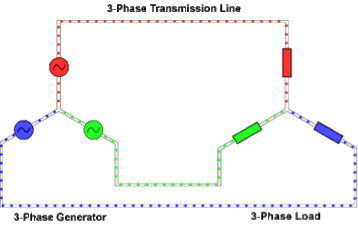
ï‚· Power Transmission and Distribution System:
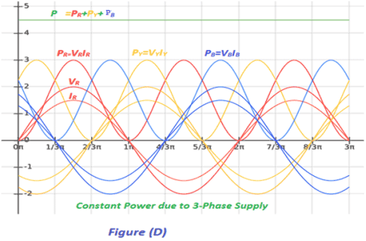
Three-phase system is used in power transmission because less amount of conductor is used to transmit electrical energy to different places.
Three conductors carry 3 alternating currents peak values of which reach at different intervals of time. If a conductor is taken as a reference point, there is a delay of time by one third and two third of a cycle of the current for the remaining two currents. Because of this delay in the available phases, constant power is transferred over each cycle of current.
There can or cannot be a neutral wire in three-phase systems. Neutral wire is used to allow a higher voltage while still supporting the appliances operating at lower single phase voltages. As loads can directly be connected between the phases so there is no neutral current wire in high voltage distribution.
 There are many factors that make three-phase system very desirable and reliable in electric power systems. In a load which is linearly balanced, the phase currents cancel each other and add up to give a zero which also helps in eliminating the neutral wire. Phase conductor carry same amount of current which means that they all can have a same size of conductor for balanced conditions. Moreover, the transfer of power in the system is constant for a linear system, it reduces the vibrations in a system.
ï‚· Generation:
Electricity is generated at the power station at around 10kV by rotating a coil in the magnetic field. In power stations, all the generators are synchronised so that they all produce electricity that oscillates together. For more efficient generation, three windings are used on the generator to produce three-phase electricity.
Sources for power generation:
For distribution, the following types of resources are available for the generation of the electricity.
- Conventional Methods:

- Thermal energy:
Thermal energy or the Nuclear energy is used to produce steam for the turbines that drives the rotating AC generators to produce electrical energy.
- Hydro-electric:
Potential of water is stored at a higher altitude and is made passed through the turbines which in turn drive the generators.

- Non-Conventional Methods:
Wind power:
Winds blowing at high speeds are used to drive the turbines that are coupled to the rotating AC generators.

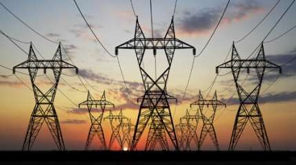
ï‚· Transmission:
Transmission has an important role between the production of power and the usage of power. Transmission lines carry high voltage electricity over long distances from power plants to the consumers. Once the power is generated. It is send to the substation in the power plant where the voltage is stepped-up using step up transformer for transmission purposes.
When the voltage is stepped up, it helps in the reduction of the transmission losses. It is then sent to the grid station from where it is further transmitted to different cities.
- Why there is a need to step up the voltage for transmission:
For transmission over long distances, transmission lines are made up of conducting materials like aluminium and power loss is always associated with these conducting materials. This is because if the current through the wire is “I” and the resistance of the wire is “R” then an amount of electrical power “I2R” is dissipated as heat. This will result in a much less power at the receiving end than the actual power generated at the station.
Thus, when power is transmitted at a high voltage, wires of low current carrying capacity are used so there is no need of thick wires that cost considerably high instead they can be replaced by thin wires that cost less.
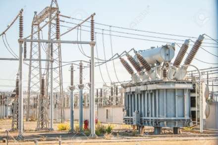
ï‚· Distribution:
Substations reduce the voltage of the electricity from the transmission lines. The power grid is connected to the different parts of the country and it distributes the power in different cities through transmission lines.
The transmitted power from the power grid is stepped-down to 110,000 volts from 230,000 volts using a step-down auto transformer. Then for the distribution of power for industrial uses, the power is again stepped-down to 11,000 volts from 110.000 volts by step-down transformer located in the streets. This reduction in the voltage increases the current in the wires and thus the losses but greatly reduces the cost of power poles and increases the safety.
The distribution substation further reduces the voltage to 230 volts or 440 volts for the local transmission for domestic purposes depending upon the need of the user. Some business and houses require two or three-phase power supply while the others only need single phase supply.
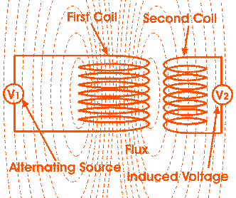
ï‚· Operation of the transformer:
Transformer works on the principle of mutual induction. According to Faraday’s Law of electromagnetic induction:
“Rate of change of flux linkage is directly proportion to the induced emf in a conductor or coil with respect to time.”
When primary winding is connected to a voltage source, an AC flows through it and which produces a continually changing magnetic flux that surrounds the winding. This changing magnetic flux flows to the secondary winding as some flux from primary winding will be linked to the secondary winding. As magnitude and direction of the flux is continually alternating, change of flux takes place in the secondary winding. According to Faraday’s law of electromagnetic induction, this changing magnetic flux produces an induced “electro motive force” or simply the “voltage” in the secondary winding of transformer therefore, a current start to flow if the circuit is closed.
The rate at which the flux changes depends upon the amount of the flux which is linked with the secondary winding of the transformer. Therefore, it is important to link all the flux from the primary winding to the secondary winding of the transformer. It can be done by putting a low reluctance path which is usually common to both of the windings and that low reluctance path is known as the core of the transformer.
Three-phase Induction Motor
Introduction:
Electric motor is a device which performs the operation of converting electrical energy into a mechanical energy. The induction motor is known as a three-phase AC motor which is widely used in the industrial applications as they are:
- Self-starting.
- Their construction is simple and compact.
- Less expensive.
- Require minimum amount of maintenance.
- More reliable and highly efficient.
- Additional starting motor is not required and do not required to be synchronised.
Induction motor is also known as asynchronous motor. Due to inductive coupling, the generated electromagnetic power is transferred to the secondary winding. These windings are being separated by air gap between them.
The induction motor consists of a Stator and a Rotor. The motor frame is permanently attached with windings of very low resistance. When current and voltage is applied to the terminals of Stator windings, a magnetic field is produced.
ï‚· Applications of three-phase induction motor:
Induction motors are most demanded motors in the industry. Some of their applications are given below:
- Industrial drives make use of 3 phase cage rotor motors because they are pretty simple, efficient and are not costly.
- Single phase induction motors are used where the load is comparatively smaller.
- These motors are being used in the fixed-speed load drive service.
- Induction motors can also be used as variable frequency drive (VFD) service.
- They are used in variable-torque centrifugal fan, compressor loads and pumps.
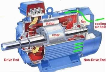
ï‚· Construction:
Induction motors are very demanding motors in the market and its construction is quite simple. It consists of the following parts:
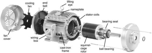
1. Stator:
The stator is known as the stationary part of the motor. It consists of numerous number of stampings that are slotted to receive stator windings and stator winding is present in the stator and a 3 phase voltage supply is supplied to the winding. The stator is wound for a known number of poles and that number can be found from the speed which is required by the motor. Less number of poles are required for greater speeds and more number of poles are required for lesser speeds.
2. Rotor:
Rotor is known as the rotating part. Rotor is connected to the load with the help of a shaft.
Rotor further consisting of 2 types:
- Squirrel cage rotor.
- Wound rotor or slip ring rotor.
In this assignment, I will only explain the construction of squirrel cage rotor.
- Squirrel cage rotor:
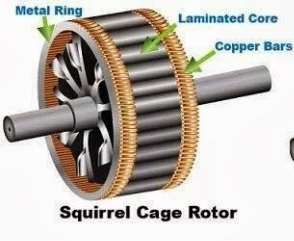 Squirrel cage rotor is very simply constructed. It consists laminated core which is of cylindrical shape and having parallel slots on it. To make the working of the motor smoother and quitter, these slots are a bit skewed which stops the magnetic locking of the stator with the teeth of rotor. Rotor conductors are present in these slots which are bars of copper, aluminium or alloys. These bars are electrically welded with the help of copper or aluminium rings called the end rings that permanently short the bars to provide mechanical strength. This closed circuit resembles to a cage and thus this type of stator is named as squirrel cage rotor.
The rotor resistance is very small because the bars are shorted and it is impossible to add an external resistance. As the slip rings and brushes are absent in this type of rotor hence its construction is quite simple and easy and thus it is most commonly used in the industry.
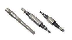
- Shaft:
Shaft is used for transmit the torque to the load and is made up of steel.
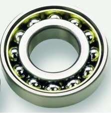
- Bearings:
Bearings are used to provide support and to locate the rotor. It also helps to keep the air gap small and to transfer loads from the shaft to the motor.
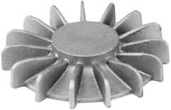
- Cooling fan:
When an electric motor operates, it produces heat during its rotation and in order to reduce the heat cooling fan is used which regulates the temperature of the motor to the minimum.
-
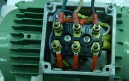 Terminal box:
Terminal box is used to provide external electrical connections to the induction motor. It provide connection between the wires from the motor to the wires from the external electrical device.
ï‚· Operation of 3 phase induction motor:
The name three-phase induction motor is derived considering that current is induced in rotor of motor by a changing magnetic field.
Stator of the motor consists of offset overlapping of the windings by an angle of 120 degrees. When the stator is connected to the three-phase AC supply, a rotating magnetic field is created that rotates at the synchronous speed.
The synchronous speed is defined as follows:
“The speed of rotation of the magnetic field in a rotating machine is known as synchronous speed. This speed depends upon the number of poles and the frequency of the machine.”
Synchronous speed is determined by the number of poles and the frequency of the power supply and can mathematically be expressed as:
n = f(2/p)
where
n = rotation speed of the shaft
f = frequency
p = number of poles
By the Faraday’s law of electromagnetic induction:
“When there is a changing magnetic field present around any circuit an emf is induced in the circuit due to the changing magnetic field. “
If themagnetic field passes through the air gap and cuts the rotor windings which are stationary, an emf is induced in the rotor. As the rotor is either short circuited or closed by making use of an external resistance, current starts to flow through the rotor due to the induced emf.
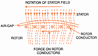
The rotor conductors carrying current are then placed in the magnetic field and thus a force acts on the conductors of the rotor. Sum of all these forces produces a torque which force the rotor to rotate in the same direction as of the magnetic field.
In three-phase induction motors, the speed of rotor is less than speed of the stator field speed (synchronous speed) and this difference in speed is because of the load on the motor. The rotor speed should never become equal to synchronous speed because if it happens there will be zero relative speed and thus zero emf will be produced there in rotor and current will start to flow and therefore zero torque will be produced.
ï‚· Crawling:
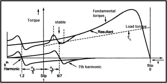
Crawling is an important characteristic that is shown by an induction motor. It is because the machine does not work properly or is faulty, that ultimately means that either the machine is running at slow speed as compared to its synchronous speed or it is not taking the load, this is known as crawling. Resultant speed of the machine is about 1/7th of the synchronous speed. The fact of this is stator winding flux waves are not purely sin waves. However, it is a complicated wave which consist of fundamental waves and harmonics such as 3rd, 5th, 7th etc which are odd. These fundamental waves resolve synchronously at Ns speed. The 3rd, 5th, 7th harmonic may possibly rotate in the backward direction or the forward direction at Ns/3, Ns/5, Ns/7 speeds. Therefore, with fundamental torque, h harmonic torques are also developed.
In the balanced 3-phase system, 3rd harmonics are absent. So rotating field and torque is not produced by 3rd harmonics. The motor torque is consisted of three components:
- Fundamental torque which will have the synchronous speed of Ns
- The 5th harmonic torque which will have the synchronous speed of Ns/5
- The 7th harmonic torque which will have the synchronous speed of Ns/7.
Torque which is produced by the 7th harmonic will reach up to its maximum positive value somewhere under the 1/7 of Ns. Slip will be high at that point. When the motor reaches up to this stage, it does not runs to its normal speed and continue to rotate at a much lower speed than the normal speed of the motor.
ï‚· Friction:
Stator of the induction motors have two basic losses: Stator iron losses and Stator losses.
The stators iron losses include eddy current loss and hysteresis loss. Rotor losses comprises of rotor copper losses and rotor iron losses. Friction losses at bearing and slip rings are the other losses on the rotor side.
The losses in the stator iron depend on the two factors which are the supply frequency and flux density. The frequency of the rotor current gives the rotor iron loss. Frequency of the rotor current is dependent on the speed of the rotor of the machine. The frequency of rotor current is very small and the iron losses of the rotor are negligible.
When electrical networks, devices and equipment are in operation, they are often subjected to various faults. When a fault occurs, it deviates the voltage and current values from normal values or states. The power system lines carry normal voltages and currents under normal conditions which indicates a normal operation of the system.
But when electrical fault occurs in electrical networks or equipment, it causes a large amount of current and voltage to flow through the electrical device that can damage the devices. It can cause major destruction if the fault is not cleared on time because when a fault occurs, it changes transfer characteristics such as impedance of the machines from their existing characteristic values.
The type of faults is classified by the combination of the conductors or buses that are faulted together. These faults can be classified as bolted faults of the faults that occur through impedance such as an arc.
There are four types of faults in three phase systems which are as follows:
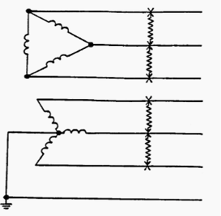
- Three phase bolted faults.
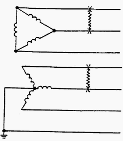
- Bolted line to line faults.
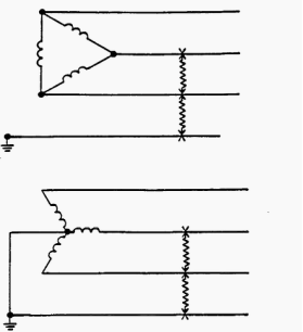
- Line to line to ground faults.
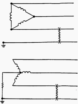
- Line to ground faults.
1. Three phase bolted faults:
In three phase bolted fault, three conductors are held together with an impedance of zero in-between if they are bolted to each other. The fault current magnitude is equally balanced with in all the three phases for a balanced symmetrical system. As this type of fault yields maximum short-circuit current, its results are used in the selection of protective devices.
2. Bolted line-to-line faults:
This fault is not balanced within the three phases and its fault current is often calculated to get equipment ratings because the magnitude of the maximum fault current is not provided by this fault. We can calculate the line-to-line current by multiplying the three-phase value by 0.866 when the impedance Z1 = Z2
3. Line-to-line-ground faults:
These faults are basically line to ground faults that are escalated to include a second phase conductor. This fault is an unbalanced fault. The double line to ground fault currents have magnitudes that are greater than the line to line faults but are less than those of the three phase faults.
4. Line-to-ground faults:
These faults are the types of the faults that occur mostly and they are usually cause the least disturbance to the system. The faulted phase current can range from zero to a slightly greater value than the current of bolted three phase fault.
Example of faulted three-phase system:
There are many causes of faults in the electrical systems some of them are given below:
- Lightning or ionizing air.
- Two or more wires blown together in the wind.
- Plants or animals come contact with the electrical wires.
- Spray of salt or the pollution on the insulators.
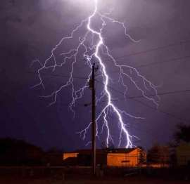
- Lightning strike:
There are around 30 million lightning strikes in the US every year and a single typical stroke can have up to 25,000 amperes current with rising time of 10µ seconds which then dissipates in 200µ seconds. There can be multiple strokes in one flash which causes the flickering of the lightning and whole event last up to one second.
After the lightning stroke energy has dissipated, the connection path is maintained by the ionized air which results in high fault currents which can often range up to 25,000 amperes. When this happens, the relays at both the ends of the line detect high currents within one or two cycles (typically 16 ms) and signal the circuit breakers to open the line and there is decrease in the voltage in the nearby locations.
Within additional one or two cycles, the circuit breakers open to de-energize the line and breaks tens of thousands of amperes of the fault current. When the lines are removed the voltage usually return to its normal values. The circuit breakers try to restore the faulted line to service by reclosing after several seconds.
As the fault currents are very high, they cause damage to the electrical equipment due to both thermal and mechanical purposes.
Fault free three-phase system:
The system is fault free when there is normal current and voltage flowing through the lines and there is no faulted current in the system. Any system which is working properly and have no faulted current is known as fault free system and in this state, all the three-phase line carry the equal amount of the current which shows that there is no fault in the system.
Faulted and Fault free three-phase system in terms of Neutral Current wire:
Neutral wire in a three-phase system allows the system to use a higher amount of voltage while supporting the single-phase appliances operating at a lower voltage on the same time. In three phase systems, each phase is separated from the other phase by an angle on 120 degrees and thus when one line acts as a forward path for the current the other two can act as a return path. For a higher voltage distribution system, there is no neutral wire as the loads can simply be connected directly to the phases but for power distribution on a relatively lower voltage, neutral wire is used. When the neutral wire is present in a three-phase system, each phase can be used as a single-phase system. When the unbalanced load or fault occurs, the unbalanced current flows through the neutral wire leaving the phase to line voltage applied to the other appliances the same. As the current from one phase cannot enter to the other two phases present in the system, it simply flows through the neutral wire present in the system.
Advantages of Neutral Wire:
- Reliable:
When a fault occurs in any one of the phase of the three-phase system, the other two phases can be used once the fault is removed. As it is known that no phase can feed the power to the other phase under unbalanced condition, there will be imbalance load present between the phases.
- Flexible:
This system is flexible in a manner that all of the household appliances do not require the same amount of voltage to operate. The loads can be switched off irrespective of the load on the other phases.
- Repairing the fault:
Maintenance and repairing of this system is quite easy as if the fault occurs only one phase needs to be shut down and the other two phases can be used while the fault is being repaired and the complete blackout condition can be avoided.
Considering task P1.1 and P1.3:
As the circuit given in task P1.1 is a fault free system, the neutral current through the neutral wire is equal to 19.39 106.50 A.
For task P1.3, it is given that the V1 become open circuit or is at fault so, the neutral current through the neutral wire increases and is calculated as equal to 24.77 111.80 A.
Conclusion:
As from the above results it can be seen that if one of the phases become at fault, the value of neutral current increases through the neutral wire. In this way the other two phases can be used till the fault is cleared and there is no need to shut down the whole system because the load gets distributed between the two phases.
- Unknown. (Unknown). Basic Electrical Engineering. Available: http://www.itacanet.org/basic-electrical-engineering/part-15-transformers/. Last accessed 24th Nov 2016.
- Unknown. (Unknown). Three-phase Transformer Circuits. Available: http://www.itacanet.org/basic-electrical-engineering/part-15-transformers/. Last accessed 24th Nov 2016.
- Unknown. (2014). CHAPTER 3 – THREE PHASE TRANSFORMERS.Available: http://federalpacific.com/training/transformer-basics/chapter-3.htm. Last accessed 24th Nov 2016.
- Wayne Storr. (2016). Transformer Construction. Available: http://www.electronics-tutorials.ws/transformer/transformer-construction.html. Last accessed 24th Nov 2016.
- Wayne Storr. (2016). Multiple Winding Transformers. Available: http://www.electronics-tutorials.ws/transformer/multiple-winding-transformers.html. Last accessed 24th Nov 2016.
- Shivam Pandey. (2016). What is the difference between Hysteresis loss & Eddy current loss?. Available: https://www.quora.com/What-is-the-difference-between-Hysteresis-loss-Eddy-current-loss. Last accessed 7th Dec 2016.
- Unknown. (2016). Three Phase Transformers. Available: http://www.electronics-tutorials.ws/transformer/three-phase-transformer.html. Last accessed 7th Dec 2016.
- Unknown. (). Single Phase, Three Phase Transformers. Available: https://canadatransformers.com/transformer-phase/. Last accessed 7th Dec 2016.
- Chris Woodford. (2016). Electricity transformers. Available: h