WebGL Based Medical Imaging Application
As the information technology advancing, new technologies are being introduced in 3-dimensional field. In recent years, the 3D model visualisation has attracted many people. However, the visualisation of 3D models remotely in web browser has been challenging because of various reasons. Most 3D remote visualisation technique suffer from latency where 3D data (in uncompressed format) must be downloaded in browser at site and this data downloading time is large and critical for 3-D data display. The other challenge is the usage of heterogeneous devices where a low powered device is not computationally efficient and limited in resolution can’t achieve the same display quality as a high power device e.g. A PDA cannot process and display a 3-D object as efficiently as a standard intel processor can.
This project aims at the visualisation of medical data from CT and MRI over web. A CT scan or MRI of a 3D object (e.g. human skull, liver or tissue) consists of hundreds of slices stacked over each other.
The implementation is based on the traditional client-server architecture. At server side the standard marching cube algorithm extracts polygonal meshes from slices and these meshes are compressed before they are transmitted over internet since uncompressed data degrades latency. A progressive compression algorithm is used to achieve high data compression and different level of details (aka LODs). Because of progressive compression, the end user need not wait for downloading the complete object in the browser, but gets a coarser version of the 3-D object first which improves when more level of details are added with time. So, 3-D object is presented at different resolutions in a progressive manner. A cross-browser JavaScript library Three JS(WebGL based) is used to achieve this interactive display of 3-D object.
Acknowledgements………………………………………………..ii
Declaration……………………………………………………..iii
Abstract………………………………………………………..Iiv
Table Of Contents…………………………………………………v
Table of Figures………………………………………………….vi
Chapter 2 – Technical Background
2.3 Remote 3D visualization on the web………………………………….…………………10
Chapter 3- Analysis Techniques
Chapter 4 – Conclusions and Project Outline
 Table of Figures
In medical science, radiographic images are primarily used to detect the diseases or any abnormalities present in human body. Different modalities were introduced with time to detect these conditions e.g. Computed Tomography (CT) is used primarily in diagnosing cancers, Magnetic Resonance Imaging (MRI) technology is used to create thorough images of any organ and tissue. Some of other techniques used for diagnosis are Positron Emission Tomography (PET) scan, Ultrasound and Single-photon emission computed tomography (SPECT). The radiographer looks at the images produced by these and diagnose the patient and further decisions of treatment are based on accuracy of these images. With the advancement in IT, it is now possible to get this medical data over web. In this project, there is a need of 3-dimensional data visualisation through popular web browsers.
MAGLO and Lee [1] take elementary approach to describe a 3-D visualisation scheme. They divide the visualisation in three prime areas i.e. 3-D streaming, 3-D compression and 3-D adaptation.
1.1 3-D Streaming
The continuous real-time delivery of a 3-D content over network and providing a visual quality as if data is stored locally is termed as 3-D streaming. S.-Y. Hu [2] classify 3-D streaming is into four categories: (i) Object streaming which considers 3D objects as stream objects which are continuously updated/improved in resolution as the time progresses. (ii) Scene streaming which is an extension of the object streaming where multiple objects are placed arbitrarily in space and at one time only selected objects are send over pipes and visualised. (iii) Visualisation streaming is useful where the data volume is quite high and we need an environment which have high performance networks and graphic servers for this much data volume so this streaming approach is not suitable for internet which is limited bandwidth. (iv) Image-based streaming where the 3-D content is stored at server and the client receives the 2-D images in real time. This approach is preferred where the client has limited computation power. Chang and Ger. [3] discuss an image based rendering where they prefer low power mobile devices for display resolution. For nonimage-based rendering programs they propose client-server architecture.
1.2 3-D Compression
3-D compression is divided into two categories:
Standard compression where full data is compressed first and then transmission is started. So the end user will encounter latency since there is a delay (the time taken to compress the complete object) in displaying the data at its site.
Progressive compression where compression is achieved in multiple steps, i.e. progressively. The client starts receiving the data without any wait. The first display at local site is coarser version of the 3-D object which improves when more data is compressed and transmitted from the remote site. So, client gets multiple resolutions of the same 3D object over time. This scheme does not introduce any delay or waiting so latency is reduced by a great margin as compared to standard compression technique.
1.3 3-D Adaptation
3-D data adaptation is to give the end user the best visualisation quality where the optimum set of 3-D object is selected to improve the display quality.
In further chapters, we will be identifying the technologies/algorithms which are best suited for this project.
We have medical slices from CT scan or MRI. We first need to process these slices to extract the data. A standard marching cube algorithm converts slices into polygonal meshes.

Figure 2.0. Marching cube algorithm concept
Resource: self-created
The Lorensen[3] presents a standard marching cubes algorithm which extracts polygonal meshes of constant density surface from a volumetric data set(i.e medical slices). The information extracted from slice samples depends on which modality is used for data acquisition. Some of the famous modalities are CT, MRI and SPECT.
An imaginary cube is generated from 4 pixels from each of the successive slices and marching cube determines the intersection of this imaginary cube with the surface of the object and then algorithm marches to the next cube made from next 2 slices. The surface will intersect the cube edges when one vertex value is greater than the value at the surface and other is lower. Since there are 2 state possible for a surface and a cube has 8 vertices, there will be 2^8 = 256 ways a surface can intersect the cube. Considering the complementary and rotational cases the 256 reduce to 15 cases as shown in Figure 2.1.1. For each case an eight-bit index is created where each bit represents the vertex value where set bit defines the high density point and clear bit represents the low density point. The resulting information is used to populate a 256-element look-up table that maps voxel configurations with edge lists and using linear interpolation technique and densities at each edge vertex the algorithm finds out the intersection of the surface in the cube edges. Figure 2.1.2 shows the function of lookup table. A unit normal is calculated at each cube vertex and this normal is interpolated with the triangle vertex generated by these 15 configurations.
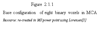
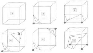
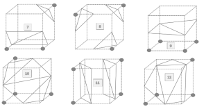
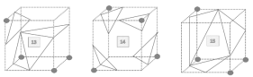
 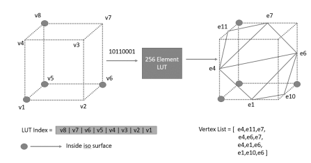
 Figure 2.1.2 Operation of the MCA lookup table
The standard marching cubes algorithm offers some disadvantages: (i) holes are generated (ii) sharp features within cells are lost (iii) created mesh may contain badly shaped triangles which requires mesh optimization.
As mentioned, standard marching cube algorithm suffers from some disadvantages such as hole generation. It does not differentiate between the vertices which are on surface and which are inside surface so, Jin and Wang[5]Â exploit this further and redefine the base configurations by considering a second index which treats the two vertices(i.e. inside and on surface) differently. The improved MCA shows a reduction in holes generation as compared to the standard approach.
The standard MCA still suffers from long thin triangle, Schaefer & Warren [6] proposed a dual surface concept where each vertex in standard marching cube is surrounded by a quad patch which is the dual of standard MCA. The Dual MC surface removes the any abrupt changes.
So with the improved versions of Marching Cube algorithm one can get the accurate polygonal meshes from volumetric datasets which don’t suffer from any problems and can be compressed using standard techniques (discussed next).
The polygonal meshes generated from MCA contains millions of triangles and it will take too much time to load into end user’s browser. So, there is a need to compress this data to improve time latency and quality of service. But before understanding the compression let us understand about the data which is important to preserve to achieve reconstruction of the same object at a different site.
2.2.1What data to be preserved in compression
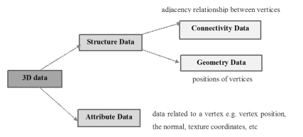
 Figure 2.2.1: Data preserved while compressing mesh
When we start compressing the meshes the model has to go through decompression before it is displayed at the other side so, mesh has to be compressed while preserving the topology and any appearance attribute. Figure 2.2.1 shows the important data catogories that should be preserved in compressed mesh.
2.2.2Decimation Algorithm
Schroeder [7] explains a decimation algorithm, which reduces the number of triangles in a mesh. The reduced mesh must maintain the original mesh topology and it should be good geometric approximation of the original mesh. Multiple passes are made through the mesh vertices and during each pass every triangle is candidate of removal which is decided based on specified decimation criterion. Although this algorithm provides a good reduction percentage in triangle but high frequency featured were blurred because of the global averaging applied. Also the swap space available at the graphics hardware is limited by these many triangle reductions.
2.2.3Progressive Compression
The idea of progressive compression is to get the low resolution of an object first and improving it as data is incrementally received. This is useful particularly in case of remote visualisation because it allows to have the same display quality across heterogeneous devices used at the client side. Also, the client does not need to wait for the full data to be downloaded at its side so latency is improved.
Hoppe [8] suggested the progressive compression technique for the first time and explains the progressive meshes (aka PM) with the simple concept like edge collapses (and reverse operation vertex split). The idea behind edge collapse is to merge two connected vertices as shown in Figure 2.2.2. A sequence of successive edge collapses on meshes convert an initial mesh into comparatively coarser versions as we move as shown by Figure 2.2.3
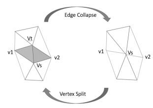
 Figure 2.2.2: Vertex split and edge collapse
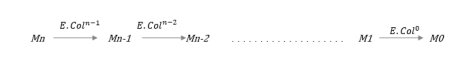
 Figure 2.2.3: Successive edge collapse leading to coarsest mesh (i.e. M0)
The edge collapse operation is invertible which means we can convert back to original mesh using vertex split which is exact opposite of the edge collapse. This progressive compression is lossless since the exact model is recovered back after all records are received at the receiver. Also, the quality of the resulting display depends on the optimum selection of edges which are collapsed. Hoppe achieved the good graphic quality of a 3-D object using the PMs where different LODs were visualised at the receiver end.
Based on Hoppe’s PMs, Taubin [9] proposed a scheme called Progressive Forest Split(aka PFS) where granularity was compromised to improve the bit rates of PM. This scheme differs in two successive LODs by a group of vertex splits as opposed to one in PM. In general, the compression is higher when we minimize the number of LODs so PFS technique achieves a good compression with bit rates 30 bits per vertex (aka bpv) with several LODs. In the standard progressive mesh(PM) approach the cost of encoding every vertex split is high because more bits are needed to identify the vertex that needs splitting. PM uses approximately 35 bpv for encoding a mesh so PFS a slight improvement. The PFS is refined further by a technique called CPM (Compressed Progressive Meshes) proposed by Pajarola and Rossignac[10]. Similar to PFS the mesh refinement is achieved in batches but using an efficient butterfly subdivision scheme where the neighbouring and already decoded vertices are used to predict the location of new vertices. When performed on different models, although CPM suffers in terms of connectivity coding but outperforms overall better than the PM/PFS approaches since it improves drastically in geometric compression aspect. In terms of bpv it achieves the bit rate of 25 bpv for the medium/large size meshes. Also, it provides a good approximation of the original object much faster and in less number of level of details aka LODs (typically in the range of 7-15).
Li and Kuo[9] backed up the ideas on the progressive compression algorithm and suggested the embedded coding which encodes the geometric and connectivity data in interwoven manner. The authors applied the algorithm on complex geometric models at different compression ratios and achieves a good display quality with a compression ratio of 20:1.
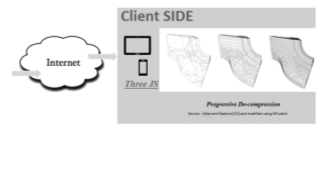
Alliez and Desbrun [12, 13] propose a higher compression efficiency and improved granularity as compared to PM, PFS and CPM for transmission of triangular meshes. The authors use valence (vacancy created by removing the vertex) driven compression where a mesh is decimated layer by layer using vertex removal. During this process of compression, the removal of smaller valence vertices is preferred because experiments show that removal of high valence vertices may result into badly shaped triangles (after retriangulation) or may change the topology of the mesh. So, the authors consider removal of the low valence vertices. Patch borders remain unchanged when a vertex is removed from the patch therefore, these borders are known to the encoder side which has the original patch and to the decoder side which has the patch with same borders but retriangulated patch. The objective is to achieve a one valence per vertex and author uses the smoothness of meshes and achieve bit rates around 20 bpv. This progressive compression takes significantly longer time to reproduce the full resolution of the model the prime reason being the refinement steps needed with every new refined resolution model received.
Marcos and Francisco [14] discusses the different hierarchal compression algorithms that evolved with time and suggest to use the wavelet transforms. The authors further discuss the concept of wavelet based compression algorithms by taking the ideas from Morán [15] and Khodakovsky[16]. Two meshes are said to be homoeomorphic if they are topologically equivalent. The authors first obtain the irregular base mesh from the original mesh. This base mesh is homoeomorphic with the original mesh. Every triangle in the base mesh is divided into 4 triangles recursively and the newly generated vertices are positioned in the original mesh. So, the geometrical information is contributed by the base mesh and the wavelet coefficients of two successive LODs. The wavelet coding scheme further improves the compression by 15:1.
In most of the compression schemes the geometry coding is based on the underlying connectivity but progressive coders were introduced where connectivity coding is based on underlying geometry of the mesh. Gandoin and Devillers[17] proposed such a geometric algorithm where the geometric information was encoded using kd-tree-based cell subdivisions and connectivity information was encoded using vertex splits.
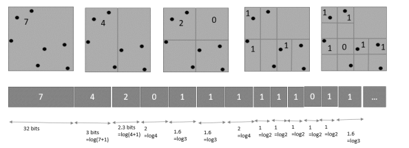
 Figure 2.2.4: kd-tree-based geometry coding in 2D space
As shown in Figure 2.2.4 the geometric coding is done in progressive manner from one LOD to another LODs. Every time when a parent cell is subdivided into two child cells, the number of cells in any one of the child cells are encoded. This cell subdivision is recursively repeated, until we reach a condition where every cell contains at max one or zero vertex. Once the geometric coding for one cell division is complete, the connectivity coding is done by encoding the topology change after every cell sub division using vertex split. So both connectivity and geometric encoding is done in progressive manner. By using kd-tree-based subdivision geometric encoding requires 15.7 bpv and connectivity encoding requires 3.7 bpv at a 12 bit quantization resolution. This is one of the best progressive mesh coders where the mesh can be regenerated in lossless manner still it suffers from two drawbacks. (i)Â For reconstruction of a mesh, the number of vertices in a cell are not important, its sufficient to know if the cell is empty or not. So, for higher level tree there is overhead of more coding bits while the same can be accomplished using less coding bits ( 1 or 0). (ii) there is an equal treatment to cell subdivision which is not optimum in terms of reconstruction since few cells may produce less distortion when subdivided so those should be given preference.
So Peng and Kuo[18] resolved these drawbacks using the octree (OT) decomposition based mesh coders. In 3-D case of kd-tree-based geometry encoding each 3-D cell is subdivided into 3 sub divisions along three planes ie. XY, YZ and ZX plane but in OT based subdivision we divide the cell into eight(oct means 8) and form a octree structure of the vertices. Figure 2.2.5 shows the 2D illustration of it.
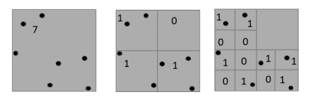
 Figure 2.2.5: octree-based geometry coding in 2D space
As shown in the figure we are concerned only if the cell is empty or not. At the end of the all cell division we get a bit pattern of all subdivisions. Also cells are selected for division based on an index parameter called importance value which depends on the valency of the cell, cell sides and length of the edges incident on the cell. So, every cell is not treated equally, cells with higher importance value reduces the distortion in final reconstruction of the mesh. The average bit rates of OT based encoders are much better than the KD-tree based encoders.
2.3 Remote 3D visualization on the web
Visualisation of 3D objects consisting millions of triangles is complex specially when the low powered devices (i.e. limited computational power, and average graphics capability) such as PDA & Tablets are used at the client site. So, indirect rendering must be used where remote resources (i.e. at server) will do all the computation and resulting data will be transmitted to the client site via network. This removes the dependency of display quality on device characteristics. A low powered device will be able to display data with same quality as a high powered device can do. But this scheme has few drawbacks such as: (i) dependence on n/w bandwidth (ii) may face latency issues (iii) client site must be capable of decoding compressed information. So, with time different technocrats and researchers came up with naïve and intuitive implementations of this rendering scheme.
Many remote collaborative visualisation schemes were introduced with time. ShareX3D by Jourdain [20] proposed a first implementation based on collaborative approach. This technique was based on two concept of transferring processed data using X3D file and HTTP usage which bypasses firewall & standard proxy limitations. However, updating information in large scenes using ShareX3D proved to be a costly affair so new collaborative schemes were sought. Niebling and Kopecki[21] proposed an improved COVISE platform(COllaborative VIsualization and Simulation Environment) where they use JavaScript and WebGL to implement the web client. They used different XML-based ASCII formats for data transfers like VRML, X3D and JavaScript vertex array which is not very efficient because of large data file sizes. To resolve the latency issue some authors proposed the data transfer using compressed data files. Isenburg and Snoeyink [22] proposed such a solution using X3D and VRML formats but their approach needs a dedicated java client at the display site. Charles and Julien [23] discusses one of the collaborative solution that combines the concept of WebGL & Web sockets where several users share the exact same view of data. A master machine has the data of a 3D model rendered and it sends scene information to visualisation server through HTTP. A user joins a collaborative session by selecting the dataset through web interface. The visualisation server puts all the connected users in the list of spectators. All spectators receive the current visualization state through broadcast and upcoming updates. Only master user can modify the state of visualisation. The frame rate achieved at different client nodes is independent of client’s location and independent of other users. A large gain is witnessed in term of networking performance using the WebSocket protocol compared to AJAX. Lamberti and Sanna[24] proposed a system where a cluster made up of high end graphics cards deals with the remote visualisation sessions. Using this approach even a limited resource device can display a 3-D objects at frame rate of 30 frames per seconds i.e FPS. The entire server cluster is managed by the OpenGL based chromium software. Hector and Razmig[25] proposes a similar framework with HTML5 and WebGL APIs in order to visualise the 3D data on low powered device. Their framework exposes a workspace (consisting of server file system) to the end-user which an end-user can access via AJAX calls. All server-side actions like file conversions, image segmentation and mesh processing is performed via Remote Procedure Call (RPC) scheme. Each action performed by the users is recorded in an xml file. The display becomes more responsive when implemented with WebGL. This framework reduces the generation time of 3D models from 4 hours to 1 hour.
Arthur and David [26] discuss Google body, which is an intuitive 3D human anatomy tool to learn about the human body. It provides user a functionality to look at anatomy layers by layers. Body parts like muscles and nerves can be viewed in the browser and it supports zooming and rotation as well. Louis and Aitor[27] discuss a semi-indirect volume rendering scheme which focuses a large part of rendering task at the end user site. Their volume rendering is based on the volume ray casting algorithm implemented in WebGL. The system obtains interactive visualisation with diverse volumetric datasets. This technique suffers from processing overhead at client side.
To provide an interactive graphics visualisation without downloading any plugin at the client side, Kostas and Spyros [28] proposes to use X3Dom technology which used JavaScript, HTML5 and X3D technologies. The data is transferred in XML at the client side and X3Dom converts this XML to a WebGL using its libraries and using the canvas feature of HTML5 the graphics is displayed. Any update in data is trarvesed to the user via websockets. However they don’t support progressive display since they are single resolution soultions. An interesting case study Max and Andre [29] compares performance of encoding formats (X3D, BG, CTM-G, WebGL-Loader i.e. Chun, CTM). The encoding formats are tested on heterogeneous devices(an iPad3 and a desktop PC) and results is drawn in terms of compactness and decompression time taken by each of the formats. WebGL-loader outperforms better in terms of bandwidth budget and target device irrespective of the devices used.
3.1Data Extraction
The different MCA versions are discussed in section 2.1. Standard MCA and its improvement versions , Dual surface MCA.
3.2Data Compression
Different standard and progressive compression techniques were discussed in section 2.2. Progressive meshes, Progressive forest split, Compressed Progressive Meshes, kd-tree-based, and Octree-based
3.3Data Visualisation
Finally, different techniques for 3D remote visualisation have been discussed. The COVISE, VRML, X3D, X3Dom, GZIP and WebGL based platforms are evaluated and WebGL based libraries are found to be better performing.
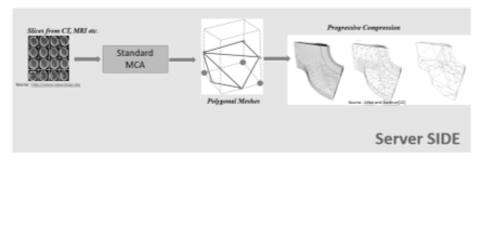
We propose a client server architecture with indirect volume rendering where at a remote site we will extract the medical data (i.e. slices) using standard Marching Cube (MCA) and convert it to polygonal meshes (made up of millions of triangles). This volumetric data will be compressed progressively in lossless manner and sent to local site via network. At local site before displaying the model, the data will be decompressed and will be displayed in browser using an interactive feature oriented WebGL based library called ThreeJS which is suitable for visualising 3-D data across browsers. Because of the progressivity, the display will be progressively refined with time. Also, the compression is slow at the remote site but decompression will be very fast at the local site. Figure 4.1 shows the pictorial description of the steps to do in the project.

References
[1]Maglo, A., Lee, H., Lavouge, G., Mouton, C., Hudelot, C., and Dupont, F. 2010. “Remote scientific visualization of progressive 3d meshes with x3d”. In Proceedings of the 15th International Conference on Web 3D Technology, ACM, New York, NY, USA, Web3D ’10, pp. 109-116.
[2]S.-Y. Hu. A case for 3d streaming on peer-to-peer networks. In Proc. Web3D, pages 57-63, 2006.
[3]C.F. Chang and S.H. Ger, “Enhancing 3D Graphics on Mobile Devices by Image-Based Rendering,” Proc. IEEE Third Pacific-Rim Conf. Multimedia, pp. 1105-1111, 2002.
[4]William E. Lorensen, “Marching Cubes: A High-Resolution 3D Surface Construction Algorithm,” Computer Graphics, vol. 21, no. 4, pp. 163-169, July 1987.
[5]Jing Jin, Qiang Wang, Yi Shen and Jiasheng Hao, “An Improved Marching Cubes Method for Surface Reconstruction of Volume Data,” 2006 6th World Congress on Intelligent Control and Automation, Dalian, 2006, pp. 10454-10457.
[6]S. Schaefer and J. Warren, “Dual marching cubes: primal contouring of dual grids,” 12th Pacific Conference on Computer Graphics and Applications, 2004. PG 2004. Proceedings., 2004, pp. 70-76.
[7]W. J. Schroeder, “Decimation of triangle meshes,” in Computer Graphics proceedings, Annual Conference Series, pp. 65-70, ACM SIGGRAPH, July 1992
[8] HOPPE, H. 1996. Progressive meshes. ACM Siggraph.
[9] G. Taubin, A. Guéziec, W. Horn and F. Lazarus, “Progressive Forest Split Compression,” SG, 123-132, July 1998.
[10]PAJAROLA, R., AND ROSSIGNAC, J. 2000. Compressed Progressive Meshes. IEEE Trans. on Visualization and Computer Graphics 6, 1, 79.93.
[11]J. Li and C.C. Kuo, “Progressive Coding of 3D Graphics Models”,Proc. IEEE, vol. 96, no. 6, pp. 1,052-1,063, 1998.
[12] P. Alliez and M. Desbrun. Valence-Driven Connectivity Encoding of 3D Meshes. In Eurographics Conference Proceedings, 2001.
[13]P. Alliez and M. Desbrun. Progressive compression for lossless transmission of triangle meshes. In SIGGRAPH ’01: Proceedings of the 28th annual conference on Computer graphics and interactive techniques, pages 195-202, NewYork, NY, USA, August 2001.
[14]Marcos Avilés and Francisco Morán, “Static 3D triangle mesh compression overview,” 2008 15th IEEE International Conference on Image Processing, San Diego, CA, 2008, pp. 2684-2687.
[15] F. Morán, “Hierarchical 3D mesh coding with subdivision surfaces,” Proc. Intl. Workshop on Synthetic-Natural Hybrid Coding and 3D Imaging, 189-192, September 1999.
[16]A. Khodakovsky, P. Schröder and W. Sweldens, “Progressive Geometry Compression,” SG, 271-278, July 2000
[17] P. M. Gandoin and O. Devillers, “Progressive lossless compression of arbitrary simplicial complexes,” ACM Trans. Graphics 21(3), pp. 372-379, 2002.
[18]Jingliang Peng and C. C. J. Kuo, “Progressive geometry encoder using octree-based space partitioning,” 2004 IEEE International Conference on Multimedia and Expo (ICME) (IEEE Cat. No.04TH8763), 2004, pp. 1-4 Vol.1
[19]Lee Haeyoung, Mathieu Desbrun, and Peter Schroeder. “Progressive Encoding of Complex Isosurfaces.”, Proceeding SIGGRAPH 2003 Papers, Volume 22 Issue 3, July 2003 Pages 471-476
[20]Jourdain S., Forest J., Mouton C., Mallet L., Chabridon S. ShareX3D, a scientific collaborative 3D viewer over HTTP. 2008 Aug.
[21] Niebling, F., and Kopecki, A. 2010. Collaborative steering and post-processing of simulations on HPC resources: Everyone, anytime, anywhere. In ACM Web3D
[22]Isenburg , M., and Snoeyink, J. 2003. Binary compression rates for ASCII formats. In ACM Web3D, 6-11.
[23]Christophe Mouton, Kristian Sonsy and Ian Grimsteadz, 2011. “Collaborative visualization: current systems and future trends”, Proceedings of the 16th International Conference on 3D Web Technology, ACM, New York, NY, USA, Web3D ’10, 101-110
[24]F. Lamberti and A. Sanna, “A Streaming-Based Solution for Remote Visualization of 3D Graphics on Mobile Devices,” in IEEE Transactions on Visualization and Computer Graphics, vol. 13, no. 2, pp. 247-260, March-April 2007.
[25] Jacinto, Hector, Razmig K Echichian, Michel Desvignes, R´emy Prost, and Sebastien Valette. “A Web Interface for 3D Visualisation and Interactive Segmentation of Medical Images” OneFit Medical, SAS, CREATIS
[26]Arthur Blume, Won Chun, David Kogan, Vangelis Kokkevis, Nico Weber, Rachel Weinstein Petterson and Roni Zeiger, Google, Inc. “Google Body: 3D Human Anatomy in the Browser” August 7 – 11, 2011.
[27]John Congote, Luis Kabongoy, Aitor Morenoz, Alvaro Segurax, Jorge Posada and Oscar Ruizk Vicomtech, Research Center, Spain, “Interactive visualisation of volumetric data with WebGL in real-time”, Newyork, ACM
[28]Kostas Kapetanakis, Spyros Panagiotakis and Athanasios G. Malamos, “HTML5 and WebSockets; challenges in network 3D collaboration”
[29] Max Limper, Stefan Wagner, Christian Stein, Yvonne Jung and André Stork. 2013. Fast delivery of 3D web content: a case study. In Proceedings of the 18th International Conference on 3D Web Technology, ACM, New York, Web3D ’13, 11-17
[30]Helwig Hauser, Lukas Mroz, “Two-level Volume Rendering,” IEEE Transactions on Visualization and Computer Graphics. vol. 7, no. 3, pp. 242-252, 2001.