Wellbore Instability and Borehole Breakout
Introduction:
Despite the development of oil and gas industry technology, Wellbore instability remains one of non – productive time that cost industry billions every year. wellbore instability has been one of the well planning stage and been studied widely (Bradley,1979; Bell, 2003; Zhang et al., 2003; Gentzis et al., 2009; Zhang et al., 2009; Ding, 2011). Drilling through a formation led to stress changing a round the borehole due to rock removal. In this analysis, mud weight pressure is the controllable parameter during the drilling. The mud weight pressure effects can cause two failure mechanisms which are shear failure (breakout) and tensile failure (fracturing), these problems consider as the main wellbore failure. Borehole breakout happens when the mud weight is lower than expected. in other word, the breakout failure occurs when the stress imposed by drilling mud lower than compressive strength. On the other hand, higher mud weight can lead to tensile failure due to invade of mud into the formation. The consequences behind these problems are stuck pipe, reaming operation, lost circulation, and sidetracking. To eliminate these problems many parameters should be considered such us rock strength, pore pressure, in-situ stress, and stress orientation. Furthermore, breakout and fracturing can be diminishing or eliminate by choosing the suitable mud weight for drilling. By using a constitutive model to predict the stresses around the wellbore connected with a failure criteria, Strength of reservoir rocks can be calculated. Hence, selection of the suitable failure criteria will consider as the main part of wellbore stability analysis.
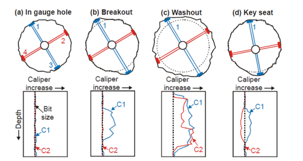
Borehole breakout is an enlargement and elongation of wellbore in a particular direction and it considers as the important indicators to predict the orientation of min. horizontal stress. This enlargement can be predicted by using 4-6 arm caliper tool, Optical imaging log, resistive image log, and acoustic image log (Jaeger et al.,2009; Bell and Gough, 1979; Zoback et al.,1985). Figure (1) shows wellbore enlargement pattern via 4 arm caliper. The 4 arms caliper has 4 pads in two calipers (pad 1 and 3) represent Caliper 1 (C1) and (pad 2 and 4) represent caliper 2 (C2). The diameter of the hole can be identified from those two calipers. Fig 1a represents an in-gauge hole cause C1 and C2 have same reading of bit size. In contrast 1C shows a severe washout in hole size and caliper reading show this enlargement.
Stand on well logs data and empirical equations, the rock strength and mechanical properties can be obtained (Rahimi, 2014). (Westergarrd. 1940) in-situ stress can be obtained by elastic characteristic equations. Also, from elastoplastic characteristic equation in-situ stress can be calculated (chang et al., 2006). As well , (LOT) and mini frac. test can help us to determine in-situ stresses (Bardley 1979b).
Many models have been built to determine the induced stress in a circular well and predict the suitable mud pressure by using Failure criteria. In this analysis, three failure criteria have been used to predict the proper mud weight in the Nahr Umr formation in southern Iraq. The three failure criteria are Mohr-coulomb, Mogi-coulomb, and modified lade.

Fig (1) Caliper log responses due to wellbore enlargement (Tingay )
Geological properties of the field and the target reservoir.
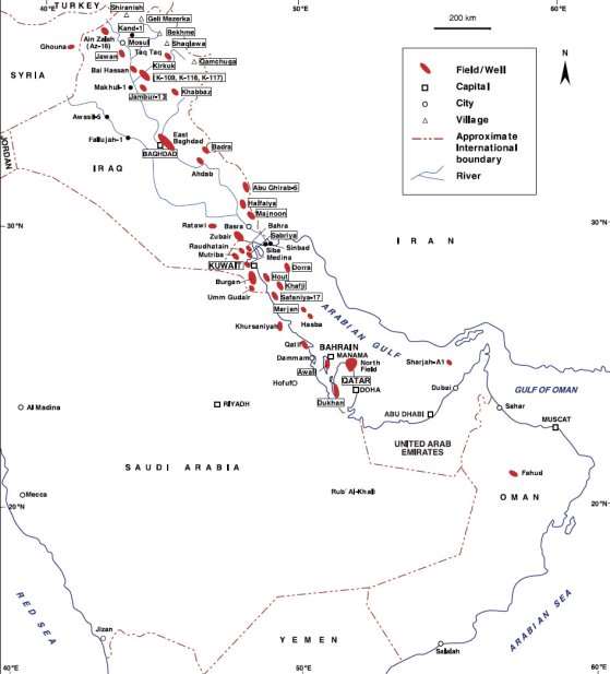
The H oil filed is a land-based field located in southeastern Iraq between the city of
Basra and the Kuwait border (Figure 2).

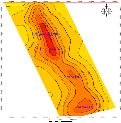
The field is an anticline that runs roughly north-west to south-southeast approximately 60 km long and 10-15 km wide. The anticline of H field has four domes divided by saddles, from the northwest to southeast these are:
- Al-Hamar
- Shuaiba
- Rafidyah
- Safwan

Fig (3) The four domes in H filed
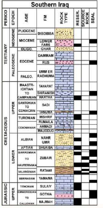
The discovered reserves are contained in five reservoirs: Mishrif, Nahr Umr, Zubair 3rd Pay, Zubair 4th Pay and Yamama. (Figure 3) represents well stratigraphic.
Nahr Umr Formation is an interesting potential water source zone due to the abundance of log data through the unit, water salinity that is compatible with the Mishrif and Zubair Formation waters, and the reported extent and strength of the aquifer. It is composed mainly of Sandstone interbedded with streaks of (Shale, Siltstone & Limestone). Average thickness of Nahr Umr formation is +/- 260 m and the porosity exceed 25% with an average of 20% permeability ranges from 1000 md to 9000 md. Depends on information from more than fifteen wells, shear failure has been noticed in Nahr Umr formation specially at the shale layers. This breakout has been shown on shale shaker and by caliper log.

Fig (4) stratigraphic of H field
Stress distribution around vertical wellbore
In case of vertical wells , the vertical stress is consider