NDT Robotic Technology
- Vortex Robot Specifications
The main objective of the CompInnova project is to deliver a novel automated prompt for a Non Destructive Testing (NDT) approach, capable for the first time to detect, evaluate and repair damages on either metallic or composite aircraft components. In this report, a detailed view of the existing state of the art in NDT robotic technology will first provide the essential technical data for determining the mechanical details of producing an advanced alternative solution to the existing related literature, whereas an overview of the determined project requirements and specifications related to the proposed NDT novel vortex robotic mechanism will be presented in the sequel.
- State of the Art
The presented research in existing NDT robotic appliances gives a solid understanding of the goal to achieve, while providing an insight in overcoming the challenges faced during such technological scenarios, thus proving essential in achieving the objective of going beyond the state of the art and providing an advanced alternative solution in NDT-related technology.
Among the most important NDT climbing robots found in related bibliography 0, 0, the VRAM Mobile Robot Platform (VMRP) 0 was a six-wheeled wall climbing robot featuring a posi-traction drive-train design for assessment and routine inspection of aircrafts (Figure 6.1). Based on a patented Vortex Regenerative Air Movement (VRAM) method, a local vortex attraction was utilized for achieving attachment on the target surface. Although the VMRP was presented to be effective in surfaces of different textures and compositions, it lacked the ability of withstanding large payload capacities, while its endurance is limited to 20-40 mins depending on the mission objectives. Additionally, the presented design did not possess the necessary sensorial equipment and the mechanical capability of performing repair scenarios of identified damages, while no experimental evaluation of its inspection capabilities on airplane shuttles has been documented.
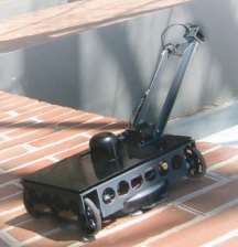
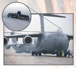
Figure 6.1: VRAM Mobile Robot Platform (VMRP) 0
The Climbing Robot with Multiple Sucking Chambers for Inspection (CROMSCI) 0 (Figure 6.2), was a robotic application designed for NDT of large concrete walls, which was consisted of three omnidirectional-driven wheels for manoeuvrability in horizontal and vertical surfaces and a vacuum system of seven controllable vacuum chambers activated via a large reservoir chamber for attachment onto the concrete walls. Testing and evaluation of NDT on composite materials was not executed, while the movement required high torque motors to generate the forces needed for the sliding motion of this heavy-weighted robot (25 kg). In addition, the vortex-inspired concept created the need of keeping a predetermined distance of the suction cups from the surface thus resulting in low payload support.
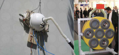
Figure 6.2: VRAM Mobile Robot Platform (VMRP) [6.4]
The Mobile Robot Platform 0, (Figure 6.3) was a robotic system designed for drilling, inspection and fastening of fixed aircraft components and assemblies. While it possessed inspection and repair capabilities through the use of several tools and the deployment of a Kuka Robot manipulator, it was constrained by its large dimensions (4.2 x 3.4 x 2.9 m) and heavy assembly (11.8 kg). This issue was addressed by an on-ground movement system via electric tugs and a vertical sled elevation system to a maximum height of 1.75 m, since such a design approach makes the attachment onto the aircraft for NDT inspection extremely challenging.
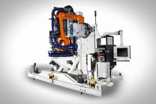
Figure 6.3: Mobile Robot Platform 0
The Air-Cobot 0 (Figure 6.4), was an inspection robot possessing a two-unit controller, one for the driving of NDT scenarios and one for navigation purposes. Inspection and damage assessment was performed via PTZ camera and 3D acquisition sensorial equipment, whereas navigation was achieved via 4 stereo cameras, 2 mobile lasers and 4 ultrasonic sensors. While it possessed high autonomy (approx. 10 hours) and maximum speed (2 m/s) it was constrained by the lack of climbing capability onto the testing surfaces, which was partially addressed by an elevation system of the inspection equipment to a maximum height of 2.5 m, as well as the lack of the necessary equipment for damage repair.
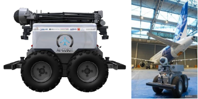
Figure 6.4: Air-Cobot 0
The C-CheckIR 0 (Figure 6.5) was an active thermography system that utilized an infrared camera for NDT and a halogen lamp for the thermal excitation of the under-inspection part, while the attachment onto the surfaces was achieved by passive suction caps. The specific application, although possessing the equipment suitable for inspection of composite materials, was characterized by the lack of repairing capabilities and the need to be manually deployed on the under-inspection structure, which highly increases the deployment difficulty and time consumption in scenarios that involves the inspection of a large dimensioned part or a whole airplane shuttle.
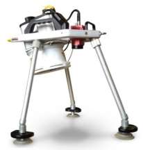
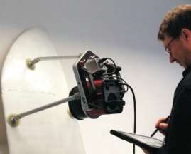
Figure 6.5: C-CheckIR 0
Lufthansa Technik presented a prototype robot for inspection of Boeing 737 Classic fuselage panels called MORFI (Mobile Robot for Fuselage Inspection) [6.8], which is presented in Figure 6.6. This research was focused on a mobile robot fitted with a thermographic inspection unit that moved past pre-programmed points of the outer skin of the aircraft fuselage. The robot utilized vacuum pads to successfully keep it attached on the surface and thus doors, windows and mounted pads were reported to be avoided during inspection. During one positioning operation the inspection was performed on four smaller areas with respect to the fuselage skin plates edges and the entire inspection cycle was measured at 30 seconds. Aside from this robot’s capabilities in NDT inspection, the MORFI is characterized by a very large mass (75 kg) due to its rigid, heavy and large-dimensioned structure, which renders the design incompatible for inspection of aircraft wing structures. In addition, the setup does not possess the equipment required for damage repair, while important application fields like inspection of composite structures made from carbon-fiber reinforced plastic (CFRP) and glass fiber reinforced aluminum (GLARE) have not yet been addressed by the company.
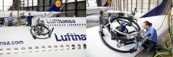
Figure 6.6: MORFI (Mobile Robot for Fuselage Inspection) [6.8]
Other approaches involved alternative robotic designs 09-0, which were focused mainly on the attachment and motion sliding techniques rather than the inspection and damage repair capabilities 0. Such approaches researched the utilization of various suction methods, such as the vibration suction technique of the Caterpillar Robot 0 (Figure 6.7), whose modular design enabled the deployment of interchangeable links, joints and attachment equipment, and the active suction mechanism of the Climbing Robot Platform 0 (Figure 6.8) that incorporated solenoid valves for suction via elastic caps.
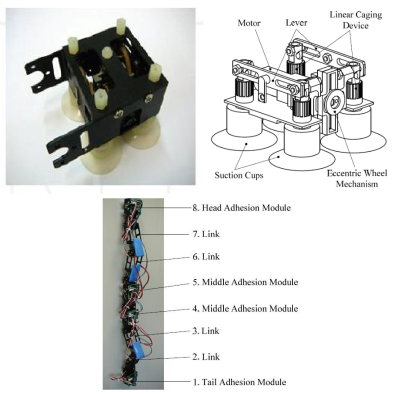
Figure 6.7: Caterpillar Robot 0
Figure 6.8: The Climbing Robot Platform 0
Alternative concepts involved the use of passive suction cups onto rail-inspired wheels 0 and magnetic wheels to achieve attachment to testing surfaces 0, as well as impeller mechanisms 0 (Figure 6.9) and thrust suction methods 0, 0 to produce a negative pressure point capable of holding the robot attached to a uneven surface. It has to be noted that such techniques create additional design challenges when having to support a large payload or when the attachment, motion and testing procedures involve composite materials that experience low friction and insufficient magnetic reaction.
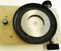
Figure 6.9: Climbing robot (left) with an impeller suction mechanism (right) 0
- Requirements and Specifications of the Vortex Robotic Design
In this section, an outline of the basic requirements of the proposed robotic design for NDT inspection and repair of composite materials in aerospace applications is presented  in detail. Given the fact that the robotic structure will incorporate various equipment required for NDT inspection and repair, its specifications will be directly affected by those of its various sub-parts. Therefore, it has to be noted that the requirements analysed below are presented from the point of conceptualization, since the design specifics are prone to several alterations prior to the final development of an optimized mechanical structure.
The restrictions regarding the weight and the permissible dimensions of the vortex robot, which will ultimately affect the design specifics of the robotic structure, will be defined according to: a) the weight and dimensions of the equipment needed for vortex generation and motion, b) the weight and dimensions of the supported payload including the sensorial equipment for the inspection system and the necessary tools needed for damage repair, and c) the regulations posed by the non-destructive testing strategy, since the attachment, contact and relative motion of the equipment with the target composite materials have to satisfy the material restrictions on maximum permissible applied force, so as to ensure that no damage will be caused on the surface of the inspected object and that any existing damage won’t be intensified.
- Vortex Generation
The robot structure should possess the ability of remaining attached to the inspected surface, independently of its curve and orientation, which will be addressed via the use of a vortex generating mechanism. Such a negative pressure generation can be achieved with different strategies that are being evaluated for their application in the proposed robot and are presented below.
SuctionCups:A suction cup is an elastic and flexible object capable of creating a partial vacuum to adhere to nonporous surfaces. Suction cups are divided into two main categories, depending on the generation of the vacuum adhesion:
- Passive: The partial vacuum is achieved via physical pressure of the cap against the desired surface. When the physical pressure is ceased, the elastic material tends to return to its original curved shape. The duration of the suction effect depends on the time it takes for the air to leak back into the cavity between the cup and the surface.
- Advantages: No additional equipment is needed. Minimum space and weight added to the robot design.
- Disadvantages: Non-permanent suction effect. The duration of successful adhesion is directly affected from the types of materials used in the cup and the desired surface, as well as the forces exerted on the equipment during different robot orientations.
- Active: The partial vacuum is achieved via the use of an external vacuum generator. Air is constantly sucked from the adhesion cavity, causing a stronger adhesion to the desired surface.
- Advantages: Stronger suction that is maintainable even in cases of non- smooth materials.
- Disadvantages: Vacuum generator and additional pneumatic equipment (sensors, solenoid valve regulators, filters etc.) are needed, which increase the setup’s overall weight and design complexity.
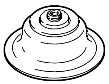
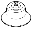
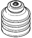
An important aspect to the efficiency of the suction caps is their shape and the material used in their development. Suction cups are available in a number of different shapes (Figure 6.10) and are being made from a variety of:
- elastomers,
- rubbers, and
- silicone-based materials,
which possess different properties depending on their:
- resistance to wear,
- intensity of stress,
- target surface properties (curvature, sensitivity), and
- environmental effect (e.g. chemically aggressive, operating temperature).
The selection of a suction cup based design for the NDT vortex robot will require the use of the materials and shapes providing best adhesion to the composite materials of the inspected aerospace assemblies and maximum resistance to wear, while ensuring a non- destructive contact with the target materials.
(a)(b)(c)(d)
Figure 6.10: Standard available shapes of suction cups: a) round flat, b) round deep, c) round with bellows and d) oval. 0
In addition, the selection of the cups’ dimensions and number should be executed by taking into account the relationship that connects the exerted suction force with respect to the geometrical dimensions of the cup and the generated negative pressure, which, in the case of active caps, leads to the optimal properties of the utilized vortex generator control equipment.
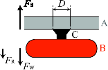
To emphasize on the importance of selecting the appropriate equipment for a cup-based design concept, a simplified test bed representation is assumed, as presented in Figure 6.11(a), which involves a target surface (A) and a payload (B) attached to it via a suction cup (C). The suction cup in this case is assumed to be round deep with a diameter D. This simulated test bed matches the most challenging case, where the vortex robot inspects the bottom surfaces of an airplane assembly, rendering the equipment in an upside-down orientation. A force analysis on this scenario yields the suction force FS, the weight of the payload FW and the reacting force from the target surface FR. In order for the payload to remain successfully attached onto the surface, FS > FW should be satisfied at all times.
Given the diameter Dof the round suction cup, FS can be computed via the equation presented below:
FS
ï°ï€ D2
 PN
PN
4s
 (6.1)
(6.1)
where PN = P– P0 is the negative relative pressure, i.e. the difference between the pressure Pthat is generated inside the cavity formed by the cup and the target surface minus the atmospheric pressure P0 = 1bar. Moreover, the regulations for the prevention of accidents (UVV) stipulate a safety factor s, which is utilized to account for:
- unknown forces due to external disturbances (e.g. vibrations due to equipment motion),
- the non-ideal shape of the suction cup (e.g. the cup’s deformation during vacuum causes a circumferential section to touch the surface, thus causing the active vacuum area to decrease),
- material properties (e.g. non-uniform, curved or rough surfaces), and
- vacuum equipment properties (e.g. fluctuations in the negative pressure’s control).
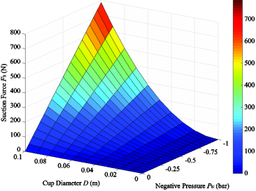
For the purposes of the presented simulation the safety factor has been set to s= 2 and the results are presented in Figure 6.11(b). This graph gives an initial approach as to the selection of the cups diameter and the required negative pressure for the generation of a specific suction force. For example, a round cup with diameter D= 0.08 m with negative pressure of PN = -0.25 bar results in a suction force of approximately FS = 125 N (12.5 kg), which means that such a selection would result in successful attachment to the target surface for the payload cases of smaller than 12.5 kg.
- (b)
Figure 6.11: (a) Simplified force analysis of the suction effect while attaching a payload (C) to a target surface (A) via a suction cup (B), (b) the suction force FS generated by the suction cup with respect to the cup’s diameter Dand the negative pressure PN.
It should be noted that the same result could be achieved via the use of multiple caps, which would result in a decrease of the required negative pressure for a given constant diameter. In this approach, the vortex robot should incorporate one or more cups of appropriate dimensions and placement in order to ensure a non-destructive contact, since concentrated large forces could result in damaging the target surface or worsen existing material defects 0. In addition, the equipment should have integrated mechanisms for isolating a suction cup in case of disconnection or loss of attachment to the surface, in order to avoid suction control failure.
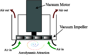
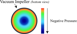
VacuumImpeller:In this approach, successful aerodynamic attraction to the target surface is achieved via the utilization of a vacuum impeller-based mechanism, which is connected to a vacuum motor (Figure 6.12(a)). The high speed rotation of the impeller causes the air flow to form a aerodynamical swirl effect that causes the pressure to drop, an effect that intensifies closer to the center of the impeller (Figure 6.12(b)). In this way, the generated negative pressure leads to an aerodynamic attraction to the target surface. It has to be
noted that for the maximum available attraction, the impeller should be selected with the proper blade profile and dimensions, while the appropriate motor type should be utilized as to be able to produce high-speed rotations 0.
- (b)
Figure 6.12: (a) Vacuum Impeller-based concept for aerodynamic attraction, (b) Distribution map of negative pressure on the bottom view of the impeller mechanism (darker colors correspond to larger values of absolute negative pressure and stronger attraction).
- Advantages: No contact with the target surface is required, which provides an inherent NDT characteristic. The use of external pneumatic equipment (e.g. vortex generator) is avoided. Results in a more compact and autonomous design.
- Disadvantages: The use of a vacuum motor and additional equipment  (sensors, motor controller etc.) is essential, which increases the setup’s overall weight, dimensions and design complexity. The suction area is limited to the center part of the impeller mechanism, which increases the difficulty of supporting large payloads due to the constant air leakage from the outer impeller sections. Larger attraction forces can be generated with the use of more powerful motors or larger impeller dimensions, which increases the overall power consumption, dimensions, weight and drag torque of the vortex robot, thus also affecting the restrictions posed on the maximum payload.
Acombinationoftheabovestrategies:A design strategy of combining both suction cups and vortex impellers could be considered, although such an approach should take into account all abovementioned specifications, which could further increase the analysis complexity of the vortex robot for successful NDT of composite materials in different orientations, curvatures and dimensions.
- Motion
The robot structure should possess the ability of moving autonomously across the inspected surface, while remaining attached to it, independently of its curvature and orientation. Another important design aspect is that the robot should also possess the mechanical ability
of changing directions. These characteristics can be achieved with different strategies, which are being evaluated for their application in the proposed robot and are presented below.
Wheel-BasedMotion:In this case, the motion of the vortex robot is achieved via a motorized wheel design approach. The appropriate selection of the wheels dimensions and the type of the motors is essential to the operation of the vortex robot and the satisfaction of the general requirements posed by the NDT application.
A wheel-based approach should ensure minimum sliding motion between the wheels and the inspected surface, although the better the grip between the surface and the wheel, the larger the friction forces are to overcome. In addition, the material of the wheels should be selected appropriately so as to ensure the non-destructive contact with the inspected material.
The need for the robot to successfully operate in different orientations due to the target
surface’s curvature will require the use of large torque servoâ€motors in order to achieve sufficient motion velocity in all inspection scenarios. On the other hand, the optimized
design of the vortex robot, via the appropriate selection of the number of wheels and their placement, should keep the torque as low as possible, since more powerful motors lead to a large increase in weight and a decrease in the maximum supported payload.
The minimum force, which has to be applied by the wheels in order to achieve motion, will be directly affected by the robot’s weight, seal friction, driving resistance and inertia phenomena. As far as the motor types are concerned, modern torque motors with the appropriate selection of the reduction ratio from the harmonic drives have the advantage of producing high torques, while having the advantage of operating in overloaded states for a short period.
Assuming the simplified test bed representation presented in Figure 6.11(a), which corresponds to the challenging scenario when the vortex robot inspects the bottom surfaces of an aircraft, a four-wheeled motion system is added with a wheel diameter d(Figure 6.13). A force analysis on this scenario yields additionally the total friction force FT and the total motor force FM. In order for the robot to successfully move onto the surface, FM > FT should be satisfied at all times, with FT = μsFS, where μs is the static friction constant.
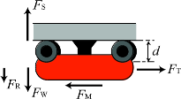
Figure 6.13: Simplified force analysis for a four-wheeled motion mechanism of the robot in the upside-down orientation.
For the critical state where FS = FW, for a robot that weights 15 kg (FW = 150 N) and assuming static friction constant for smooth surfaces μs = 0.5, would result in a necessary total motor force FM > 75 N and, thus, in 18.75 N per wheel. This force can be achieved via a combination of motor specifications with gear reduction and wheels of appropriately selected diameter. For example, a standard commercial torque motor which produces T=
0.05 Nm at f= 3.500 rpm, with gear ration providing a reduction of R= 50:1 and for a wheel of diameter d= 0.1 m is able to generate continuously 25 N per wheel by a maximum speed of 0.37 m/sec and, therefore, can provide the necessary torque for the robot’s successful motion.
The optimal selection would be a motor that can provide the necessary requirements, with the minimum operating power and, most importantly, the minimum weight so as to increase the maximum supported load. Moreover, the mechanism should possess the capability of direction changing, since the vortex robot will be required to move in two dimensions in order to satisfy various inspection scenarios.
Considering the simplifications of the above analysis, the minimum speed that the vortex robot should support will be also defined by the torque changes during the robot’s turning motion, the inspection equipment’s specifications, as well as the overall scenario requirements. By an initial estimation, which is subjected to future changes, the robot should be able to support a minimum velocity of 0.02 m/sec.
Finally, it has to be noted, that the motor-wheel mechanism should be equipped with the necessary sensors for position/velocity/torque control, as well as the ability to measure the strain that is generated via the relative movement of the wheels onto the inspected surface (e.g. via integrated strain gauges inside the wheels).
Belt-BasedMotion:Similarly to the wheel-based strategy, motors are utilized to transfer motion to toothed belts that undertake the contact with the inspected surface and the generation of movement. This solution provides a trade-off between friction and weight distribution, since the use of rails increases the contact area with the target surface and leads to larger static friction. On the other hand, a larger contact area results in better grip and more evenly distributed weight of the robot onto the surface (especially in inspection scenarios where the robot is placed on top of the aerospace assembly surface), which increases the maximum constraint of the overall weight for satisfying a non-destructive contact with the inspected material.
This mechanism should also possess the capability of direction changing, since the vortex robot will be required to move in two dimensions in order to satisfy various inspection scenarios. This can be achieved with appropriate control of the motors’ operating direction.
SequentialMotor-basedMotion:In this approach, a Cartesian motor-based robot is utilized in order to generate the motion of the vortex robot onto the inspected surface (Figure 6.14).
 Specifically, multiple suction cups, which are placed appropriately on the edge sections of the robot and on the middle platform, are sequentially turned on and off while moving the respective sections of the robot via the operation of the Cartesian robot.
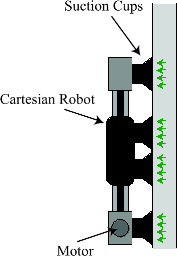
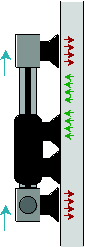
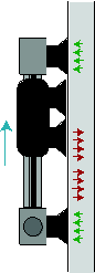
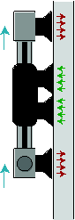


 Figure 6.14: Conceptual representation of the sequential motor-based motion via the use of suction cups and a Cartesian robot, while performing vertical movement onto the inspected surface.
The additional weight added by the Cartesian robot is considered a disadvantage of this particular approach, although the possible use of the robot structure as a support frame for the rest of the inspection and repair equipment can be considered as an efficient way of reducing the overall weight and enabling a more compact and concentrated design. In addition, the absence of multiple motors, in comparison to the approaches described above, results in lesser weight and lower energy consumption, while the absence of wheels coming in contact with the inspected surface makes this approach more suitable for NDT scenarios.
Moreover, the utilization of multiple suction cups distributes the needed suction force in order for the robot to remain attached to the surface, thus enabling the selection of either smaller negative pressure or cups of smaller dimension, while compared to the solutions described above.
As far as the motion speed of such a robotic design is concerned, a slight decrease is expected due to the sequential stages involving the time delays from the activation and deactivation of the vacuum regulators, but given the fairly large times needed for the inspection and repair, such a decrease in speed will be considered negligible to the overall requirements and desired specifications.
Finally, the mechanical challenge of the robot changing direction in such an approach could be addressed via the use of a rotational motor-based mechanism on the middle platform,
which would rotate the edge parts during the deactivation phase of the respective edge suction cups.
Acombinationoftheabovestrategies:A design strategy of combining wheels or belts in a sequential motor-based approach with the use of a Cartesian coordinate robot could be considered, although such an approach should take into account all abovementioned specifications, which could further increase the analysis complexity of the vortex robot for successful NDT of composite materials in different orientations, curvatures and dimensions.
- Design
The design specifications should be optimized so as to ensure the normal vortex robot’s operation with parallel satisfaction of the requirements and specifications posed by the NDT techniques. Specifically:
- As a general requirement, the dimensions of the vortex robot should be kept below 1 x 1 x 1 (length x width x height) meters. The target requirement is to build a robot that is as small as possible, in order to decrease the inertial effects during motion in different orientations and surface curvatures and soften the constraints on the suction and motion requirements. In addition, smaller dimensions provide the important ability of deploying the robot onto smaller disassembled aerospace parts.
- The total mass of the robot should not exceed 15 kg, whereas the robot mass without the payload (i.e. various inspection and repair components) should be constrained to 5 – 10 kg, resulting in a supported payload ranging between 5 – 10 kg. A heavy setup results in high power requirements for the attainment of successful attachment and motion, which in turn further increases the overall weight and complicates the design properties.
- Since the design target is to reduce the overall weight as much as possible, Â a modular design should be researched in order to ameliorate the payload restriction. In this approach, the different pieces of equipment for inspection and repair will be interchangeable and manually placed onto the robotic mechanism, before or during the NDT scenario. Such a design strategy would result in independently deployed equipment and would enable the use of different sensors and tools to accommodate for the identification and repair of various cases of material damage.
- The robot should be able to operate in ambient temperatures ranging from 0 – 60 oC
so as to support different conditions usually met in industrial environments.
- Safety measures should be properly incorporated in the design for encountering electrical or pneumatic power failures, by placing appropriate mechanical and software fail-safes for avoiding accidental damage to the inspected surface and to the robot equipment.
- Initial experimentation for evaluation of the design specifics should include early conceptual realizations of the inspection sensors and repairing equipment in the form of early mock-ups and their incorporation to the vortex robot mechanism.
- Final design optimization will be performed according to the requirements and specifications of the inspection equipment (e.g. workspace of the developed sensors) and possible sensor deployment strategies to satisfy the modular design approach and avoid limitations to the inspected area and on the efficiency of the deployed parts.
- Sensorial Components
As already mentioned in the above subsections, the vortex robot should be equipped with the necessary sensors for the measurement of the generated negative pressure, the rotation/speed/torque of the utilized motors, as well as the strain generated from the relative contact of the equipment and the inspected surface.
In addition, a localization method should be incorporated, which should be capable of providing accurately the position, speed and orientation of the robot. Initial experimental evaluation of the mechanical design will involve the utilization of a VICON motion capturing system 0, property of Luleå University of Technology, which will be able to provide all position and orientation measurement data at the extremely high accuracies of approximately 40 μm and 0.02 degrees, respectively. The use of such a system will enable the evaluation of the inspection and the repair capabilities of the vortex robot, which will require both high precision and adaptability to surfaces of different curvature and dimensions.
- External Equipment
Additional equipment used for the pneumatic network (vortex generator, valve regulators, pressure sensors etc.), as well as the power supply of the utilized motors and the rest of the electronic and sensorial equipment, are going to be deployed on a separate ground setup in order to reduce the weight, dimensions and design complexity of the vortex robot. Transfer of pneumatic and electrical power is going to be achieved via the use of appropriately selected and connected tubes and cables.
- Summary
The purpose of this Section was to present an conceptual outline of the specifications and requirements posed on the robotic mechanism, whose main purpose will be the successful attachment and motion onto the target surfaces, while possessing the design characteristics for incorporating properly the equipment required for the completion of the various NDT scenarios, as presented in previous Sections. First, a presentation of the state of the art in related bibliography gave a solid understanding of the goal to achieve, while providing an insight in overcoming the challenges faced during such demanding scenarios. In the sequel, the cornerstones of the proposed robotic setup’s operation were identified as the vortex generation and motion mechanisms. Specifically, an analysis of the available strategies for vortex generation was presented in detail, while giving emphasis on the design properties of utilizing different equipment (suction cups, vacuum impeller etc.) to achieve the attachment
of the setup onto the inspected surfaces. A detailed analysis was also performed on the ways to achieve motion, while remaining attached on the target surface, via motor-based strategies involving wheels, belts or hybrid sequential motion patterns, and while being presented from the scope of ensuring the satisfaction of NDT regulations. Moreover, a conceptual outline of the design specifications was presented, regarding mass and dimension restrictions, as well as modular properties and safety measures, which will prove crucial to the implementation and the successful operation of this innovative and challenging method for NDT inspection and repair. Finally, general outlines were also given regarding the sensorial components and other external equipment (e.g. supply of pneumatic and electrical power) that will further affect the final design specifications and requirements of the proposed vortex robot.
7Â References
[3.1] Andreea BORITU, Non-Destructive Inspection of Composite Structures Using Active IR-Thermography Methods, U.P.B. Sci. Bull., Series D, Vol. 73, Iss. 1, 2011
[3.2] Ibarra-Castanedo C., Genest M., Piau J.-M., Guibert S., Bendada A. and. Maldague X.
P. V, “Chapter 16: Active infrared thermography techniques for the nondestructive testing of materials,” in Ultrasonic and Advanced Methods for Nondestructive Testing and Material Characterization, C.H. Chen ed., 684p, World Scientific Publishing, May 2007.
[3.3] Carolin Hildebrandt, An Overview of Recent Application of Thermography, Sensors 2010, 10, 4700-4715; doi:10.3390/s100504700
[3.4] Colin Hockings, Infrared System Specifications – What does it all mean?, http://www.ndt.net/apcndt2001/papers/867/867.htm  [Last visited on 06/02/2014]
[3.5] Nondestructive Handbook, Infrared and Thermal Testing, Volume 3, X. Maldague technical ed., P. O. Moore ed., 3rd edition, Columbus, Ohio, ASNT Press, 2001, 718 p.
[5.1] K.B. Katnam, L.F.M. Da Silva, T.M., Young, Bonded repair of composite aircraft structures: A review of scientific challenges and opportunities, Progress in Aerospace Sciences 61, 26-42, 2013
[5.2] http://www.compositesworld.com/articles/composites-repair, posted 1/1/2014
[5.3] Yalukova, O. and Sarady, I., Investigation of interaction mechanisms in laser drilling of thermoplastic and thermoset polymers using different wavelengths, Composites Science Technology 66, 1289-1296, 2006.
[5.4] Chan CM, Ko TM, Hiraoka H., Polymer surface modification by plasmas and photons. Surface Science Reports1996;24:1-54.
[5.5] Lippert T. Interaction of photons with polymers: from surface modification to ablation. Plasma Processes and Polymers 2005; 2 (7): 525-546.
[5.6] Yao YL, Chen H, Zhang W. Time scale effects in laser material removal: a review. International Journal of Advanced Manufacturing Technology 2005; 26: 598-608.
[5.7] Bernard Q, Fois M, Grisel M, Laurens P. Surface treatment of carbon/epoxy and glass/epoxy composites with an excimer laser beam. International Journal of Adhesion and Adhesives 2006; 26: 543-549.
[5.8] Buchman A, Dodiuk H, Rotel M, Zahavi J., Laser-induced adhesion enhancement of polymer composites and metal alloys. Journal of Adhesion Science and Technology 1994; 18: 1211-1224.
[5.9] Rotel M, Zahavi J, Buchman A, Dodiuk H., Pre-adhesion laser surface treatment of carbon fiber reinforced PEEK composite. The Journal of Adhesion 1995; 55: 77-97.
[5.10] Rotel M, Zahavi J, Tamir S, Buchman A, Dodiuk H., Pre-bonding technology based on excimer laser surface treatment. Applied Surface Science 2000; 154: 610-616.
[5.11] Frank Völkermeyer, Fabian Fischer, Uwe Stute, Dietmar Kracht, Physics Procedia 12 (2011) 537-542
[5.12] B. Denkena; F. Völkermeyer; R. Kling; J. Hermsdorf: Novel UV-laser applications for carbon fiber reinforced plastics. In: APT07, International Conference on Applied Production Technology, Production of Aircraft Structures.(2007), 99-108
[5.13] F. Fischer; R. Keck; M. Kaden; L. Romoli; R. Kling: Laser as an innovative tool for laminates repair. In: Sampe Europe, 2010, Paris
[5.14] F. Fischer, S. Kreling, P. Jaschke, M. Frauenhofer, D. Kracht, and K. Dilger, Laser Surface Pre-Treatment of CFRP for Adhesive Bonding in Consideration of the Absorption Behaviour, The Journal of Adhesion, 88:350-363, 2012
[6.1] C. Alberts, C. Carroll, and W. Kaufman, “Automated Inspection of Aircraft,” Report, Office of Aviation Research, Washington, D.C., April, 1998.
[6.2] M. Siegel, P. Gunatilake, and G. Podnar, “Robotic assistants for aircraft inspectors,” Ind. Robot An Int. J., vol. 25, no. 6, pp. 389-400, 1998.
[6.3] http://www.asimo.pl/materialy/download/vmrp.pdf, VMRP Wall Climbing Robot, 2006.
[6.4] C. Hillenbrand, D. Schmidt, and K. Berns, “CROMSCI: development of a climbing robot with negative pressure adhesion for inspections,” Ind. Robot An Int. J., vol. 35, no. 3, pp. 228-237, 2008.
[6.5] T. Gray, D. Orf, and G. Adams, “Mobile automated robotic drilling, inspection, and fastening,” Technical Paper, SAE International, pp. 1-7, 2013.
[6.6] https://aircobot.akka.eu/, AKKA Research, 2014.
[6.7]http://automationtechnology.de/cms/wp-content/uploads/2015/06/irndt_application_overview_web.pdf,
Automation Technology, 2015.
[6.8] http://www.lufthansa-technik.com/tcd, Lufthansa Technik, 2014.
[6.9] R. D. Dethe and S. B. Jaju, “Developments in Wall Climbing Robots : A Review Non destructive inspection,” vol. 2, no. 3, pp. 33-42, 2014.
[6.10] K. Berns, C. Hillenbrand, and T. Luksch, “Climbing robots for commercial applications- a survey,” Proc. 6th Int. Conf. Climbing Walk. Robot. CLAWAR, pp. 17-19, 2003.
[6.11] M. F. Silva and J. a T. Machado, “A Survey of Technologies and Applications for Climbing Robots Locomotion and Adhesion,” Climbing Walk. Robot. A Surv. Technol. Appl. Climbing Robot. Locomot. Adhes., pp. 1-22, 2006.
[6.12] http://mech.vub.ac.be/multibody_mechanics.htm, Robotics & Multibody Research Group, Vrije Universiteit Brussel, 2000.
[6.13] K. Wang, W. Wang, and H. Zhang, “The Mechanical Properties of a Wall-Climbing Caterpillar Robot: Analysis and Experiment,” Int. J.Adv. Robot. Syst., vol. 10, no. 34, 2013.
[6.14] A. Subramanyam, Y. Mallikarjuna, S. Suneel, and L. B. Kumar, “Design and Development of a Climbing Robot for Several Applications,” Int.J.Adv.Comput.Technol., vol. 3, no. 3, pp. 15-23, 2013.
[6.15] Y. Yoshida and S. Ma, “Design of a Wall-Climbing Robot with Passive Suction Cups,” 2010 IEEE Int. Conf. Robot. Biomimetics, pp. 1513-1518, 2010.
[6.16] S. Nishane and A. Kale, “Designing and Development of Magnetic Wall Climbing Device in Power Station,” vol. 2, no. 2, pp. 24-29, 2013.
[6.17] L. Geissmann, M. Denuder, D. Keusch, L. Pfirter and D. Röthlisberger, “PARASWIFT – A Hybrid Climbing And Base Jumping Robot For Entertainment”, in Proceedings of CLAWAR 2011: the 14th International Conference on Climbing and Walking Robots and the Support Technologies for Mobile Machines, September 2011, Paris, France, pp. 393-402.
[6.18] J. Li, X. Gao, W. Zhu, J. Yin, and J. Yujiao, “Wall climbing robot based on negative pressure-thrust suction method,” 2008 IEEE Int. Conf. Mechatronics Autom., pp. 604-609, 2008.
[6.19] J. Xiao and A. Sadegh, “City-Climber : A New Generation Wall-climbing Robots,” Climbing Walk. Robot. Towar. New Appl., no. October, 2007.
[6.20] https://www.festo.com/net/SupportPortal/Files/10595/VAS_ENUS.pdf, Festo AG & Co.
[6.21] http://www.vicon.com/